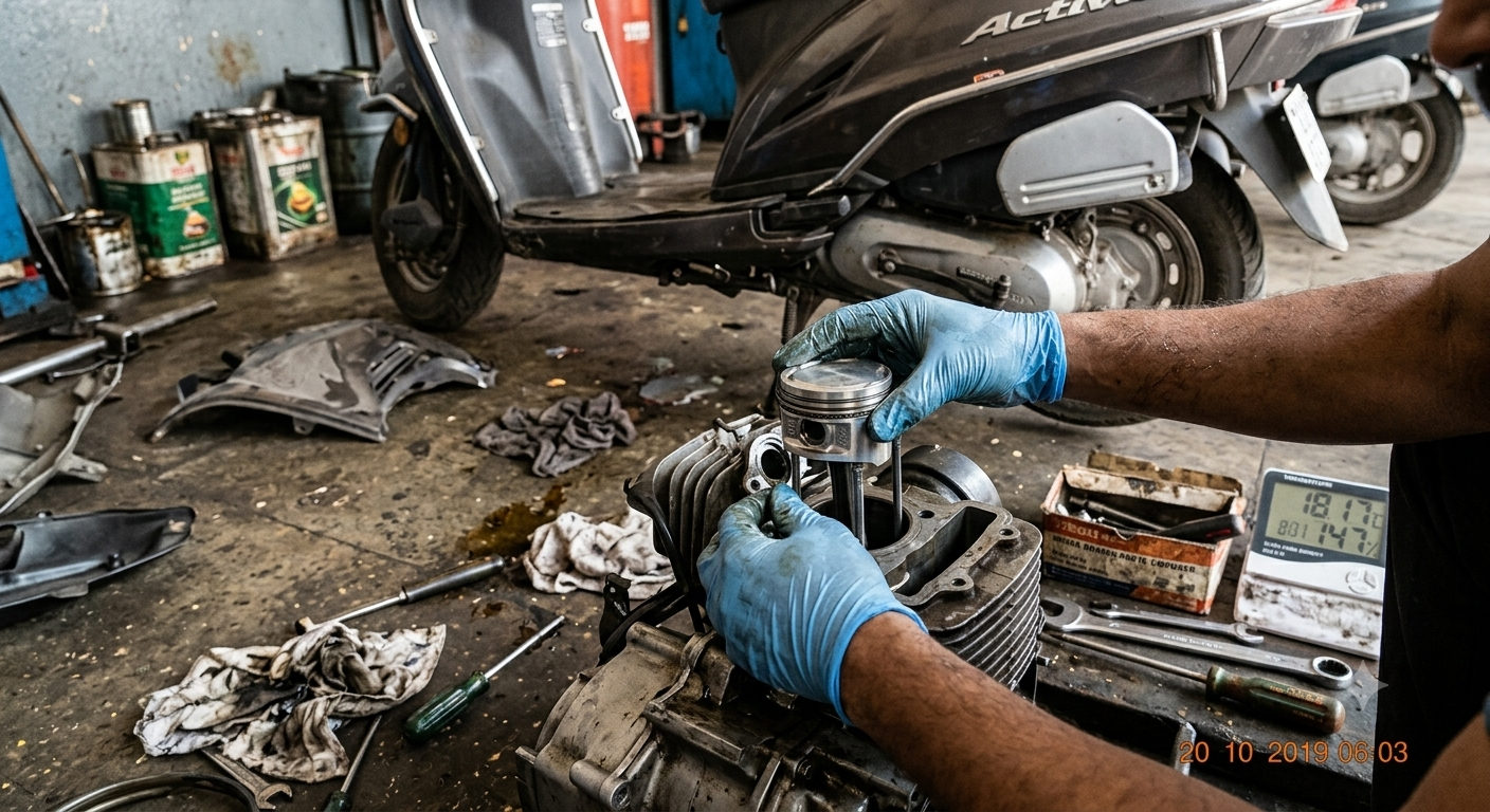
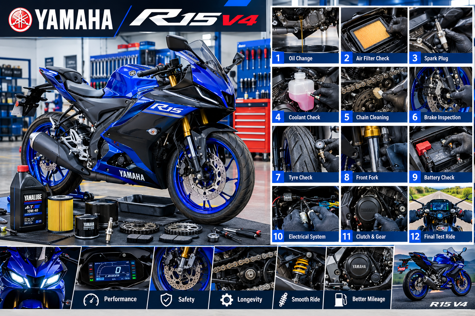
Yamaha R15 V4 Step-by-Step Service Guide

The Yamaha R15 V4 is a performance-oriented motorcycle that requires regular servicing to maintain smooth engine operation, reliable braking, proper handling, good fuel efficiency, and consistent performance. A proper service involves much more than changing engine oil. The engine, air intake, fuel system, chain drive, brakes, suspension, electrical system, tyres, and fasteners should all be inspected systematically.

This step-by-step guide explains a practical Yamaha R15 V4 servicing procedure and the important checks that should be performed during routine maintenance.

Important: Exact oil specifications, quantities, service intervals, torque values, valve clearances, and replacement procedures should always be confirmed from the service information for the specific R15 V4 model and year.

Tools and Materials Required

Before starting the service, prepare the necessary tools and consumables.

Common requirements include:

  • Socket and spanner set
  • Screwdrivers
  • Torque wrench
  • Oil drain pan
  • Funnel
  • Clean workshop cloth
  • Chain cleaning brush
  • Motorcycle chain cleaner
  • Suitable chain lubricant
  • Recommended engine oil
  • New oil filter, if applicable to the service
  • Replacement drain-plug washer, if specified
  • Air filter replacement, if required
  • Brake cleaner
  • Tyre-pressure gauge
  • Diagnostic equipment when required

For safety-critical work, use good-quality tools and the correct equipment rather than improvising.

Step 1: Wash and Inspect the Motorcycle

Start with a general inspection before removing components.

Clean the motorcycle carefully, particularly around:

  • Engine area
  • Chain and sprockets
  • Wheels
  • Brake components
  • Radiator area
  • Front and rear suspension

Avoid forcing high-pressure water directly into electrical connectors, bearings, switches, or other sensitive areas.

After cleaning, inspect the motorcycle for oil leaks, coolant leaks, damaged wiring, loose fasteners, cracked components, and other visible problems.

Step 2: Check the Engine Oil

Engine oil is one of the most important service items on the R15 V4.

Park the motorcycle securely on a level surface and follow the correct procedure for checking the oil level.

Look for:

  • Correct oil level
  • Unusual oil colour or contamination
  • Metallic particles
  • Oil leakage around the engine
  • Leakage around the drain area

Do not judge oil condition only by its colour. Oil level and service history are also important.

Step 3: Replace the Engine Oil

If an oil change is due, warm the engine according to the manufacturer’s procedure so the oil can drain effectively.

Then:

  1. Switch off the engine.
  2. Position a suitable drain pan under the engine.
  3. Remove the appropriate drain plug.
  4. Allow the old oil to drain completely.
  5. Inspect the drain plug and sealing washer.
  6. Replace the washer if required.
  7. Reinstall the drain plug using the specified torque.
  8. Add the recommended engine oil.
  9. Start the engine briefly according to the service procedure.
  10. Switch it off and allow the oil to settle.
  11. Recheck the oil level.
  12. Correct the level if necessary.

Never overfill the engine.

The correct oil grade and specification should be taken from the owner’s manual or service documentation for the specific motorcycle.

Step 4: Inspect or Replace the Oil Filter

If the service schedule calls for oil-filter replacement, replace it using the correct procedure.

Before installation:

  • Check the new filter is correct for the motorcycle.
  • Inspect the sealing surface.
  • Lubricate the filter seal where specified.
  • Install the filter correctly.
  • Tighten it to the manufacturer’s specification.

An incorrectly installed filter or damaged seal can cause an oil leak.

After starting the engine, inspect the filter area carefully for leakage.

Step 5: Inspect the Air Filter

The air filter controls the cleanliness of the air entering the engine.

Remove the air-filter element according to the manufacturer’s procedure and inspect it for:

  • Dust
  • Dirt
  • Oil contamination
  • Damage
  • Deformation
  • Improper sealing

A dirty or damaged filter can restrict airflow and affect engine performance.

If the filter is a replaceable type and is no longer serviceable, install the correct replacement element.

Do not install a damaged filter simply because it appears clean.

Step 6: Check the Spark Plug

The spark plug is another important engine-service item.

Remove the spark plug carefully using the correct tool.

Inspect the plug for:

  • Electrode wear
  • Carbon deposits
  • Abnormal colour
  • Oil contamination
  • Cracks
  • Damaged threads

Spark-plug condition can provide useful clues about combustion, but it should not be used alone to diagnose an engine problem.

Check the specified electrode gap and replacement interval for the particular R15 V4 version.

When installing the spark plug, avoid cross-threading and use the manufacturer’s specified tightening torque.

Step 7: Inspect the Cooling System

The R15 V4 uses a liquid-cooled engine, so the cooling system needs regular inspection.

Check:

  • Coolant level
  • Coolant leakage
  • Radiator condition
  • Coolant hoses
  • Hose clamps
  • Expansion reservoir
  • Radiator fins
  • Cooling fan operation

Remove dirt and debris from the radiator fins carefully without bending them.

Never open a hot cooling system because pressurized coolant can cause serious burns.

If coolant needs to be replaced, use the correct coolant and follow the manufacturer’s bleeding and filling procedure.

Step 8: Clean and Lubricate the Drive Chain

The drive chain is critical for transferring engine power to the rear wheel.

Place the motorcycle securely and inspect the chain.

Look for:

  • Excessive slack
  • Rust
  • Dry links
  • Stiff links
  • Damaged rollers
  • Uneven wear
  • Abnormal noise
  • Sprocket wear

Clean the chain using a motorcycle-safe chain cleaner and a suitable brush.

After cleaning and drying, apply an appropriate chain lubricant.

Do not simply spray lubricant over a heavily contaminated chain and consider it serviced.

Step 9: Check Chain Slack and Alignment

Correct chain slack is essential.

Measure the chain slack at the specified location using the procedure given by Yamaha for the particular model.

If adjustment is necessary:

  1. Loosen the required rear-axle hardware as specified.
  2. Adjust both sides evenly.
  3. Maintain correct wheel alignment.
  4. Recheck chain slack.
  5. Tighten the axle hardware to the specified torque.
  6. Recheck alignment and chain movement.

Incorrect alignment can cause premature chain and sprocket wear and can affect handling.

Step 10: Inspect the Front and Rear Sprockets

Inspect both sprockets for abnormal tooth wear.

A worn sprocket may show:

  • Hooked teeth
  • Sharp tooth edges
  • Uneven tooth profiles
  • Excessive wear

If the chain and sprockets are significantly worn, replacing only one component may not provide a satisfactory result.

Follow the manufacturer’s recommendations for replacing the drive-set components.

Step 11: Check the Braking System

The braking system should be treated as a safety-critical area.

Inspect:

  • Front brake pads
  • Rear brake pads
  • Brake discs
  • Brake fluid
  • Brake hoses
  • Brake lever
  • Brake pedal
  • Caliper area

Check the brake pads for remaining friction material and inspect the discs for abnormal scoring, cracks, overheating, or excessive wear.

If brake fluid is due for replacement, use the correct fluid specification and follow the proper bleeding procedure.

Never allow oil, chain lubricant, or grease to contaminate brake discs or pads.

Step 12: Check Brake Fluid

Inspect the brake-fluid reservoirs and check the fluid level.

Abnormally low brake fluid may indicate:

  • Pad wear
  • Leakage
  • Another brake-system problem

Do not simply add fluid without finding the reason for a significant level reduction.

Brake fluid absorbs moisture over time, so replacement should be performed according to the manufacturer’s service schedule.

Step 13: Inspect the Tyres

Check both tyres carefully.

Inspect for:

  • Correct inflation pressure
  • Tread wear
  • Uneven wear
  • Cracks
  • Cuts
  • Punctures
  • Bulges
  • Embedded objects

Use the recommended tyre pressure for the specific motorcycle and riding/load condition.

Do not rely only on visual inspection because a tyre can look normal while having incorrect pressure.

Step 14: Check the Wheels and Wheel Bearings

Spin the wheels where safe and appropriate and check for unusual noise or resistance.

Inspect:

  • Wheel bearing condition
  • Wheel play
  • Rim damage
  • Axle area
  • Tyre seating

Any abnormal wheel play should be investigated before the motorcycle is ridden.

Wheel-bearing replacement requires correct tools and installation technique. Force should never be applied through the wrong bearing race.

Step 15: Inspect the Front Fork

Check the front suspension for:

  • Oil leakage
  • Damaged fork seals
  • Scratches on fork tubes
  • Abnormal movement
  • Loose components

Clean the fork tubes and inspect them carefully.

Oil leaking from a fork seal can reduce suspension performance and may eventually create a safety problem if it reaches the brake components.

Step 16: Check the Rear Suspension

Inspect the rear shock absorber and linkage area for:

  • Oil leakage
  • Damage
  • Excessive play
  • Loose hardware
  • Abnormal movement

Suspension components should operate smoothly without unusual knocking or excessive free play.

Step 17: Inspect the Battery

Check the battery condition and terminals.

Look for:

  • Loose terminals
  • Corrosion
  • Damaged cables
  • Poor connections
  • Battery swelling or physical damage

If a battery charger or tester is used, use equipment appropriate for the motorcycle’s battery type.

A weak battery can cause starting and electrical-system problems even when the engine itself is healthy.

Step 18: Check the Electrical System

Turn on the ignition and check the major electrical functions.

Inspect:

  • Headlight
  • Tail light
  • Brake lights
  • Turn indicators
  • Horn
  • Instrument cluster
  • Starter operation
  • Switches
  • Warning indicators

Check wiring and connectors for damage or loose connections.

If a warning light remains illuminated, use suitable diagnostic equipment and the manufacturer’s service information rather than simply disconnecting the battery to clear the warning.

Step 19: Inspect the Fuel System

Check the fuel system for visible leaks or damage.

Inspect:

  • Fuel lines
  • Fuel connections
  • Tank area
  • Injector-related components
  • Throttle-body area

Do not attempt to open or disturb fuel-system components unnecessarily.

If fuel leakage is found, repair the problem before operating the motorcycle.

Step 20: Check the Clutch and Gear Operation

Check clutch operation with the engine off and then during a controlled test.

Look for:

  • Correct clutch free play
  • Smooth lever operation
  • Difficulty selecting gears
  • Clutch slipping
  • Unusual noises
  • Difficulty finding neutral

If the clutch is slipping or gear engagement is abnormal, further diagnosis may be necessary.

Do not compensate for a mechanical problem simply by making an excessive cable adjustment.

Step 21: Check the Throttle

The throttle should move smoothly and return properly when released.

Check:

  • Throttle free play
  • Cable or electronic throttle operation, depending on system
  • Smooth opening
  • Smooth closing
  • Return action

A throttle that sticks or fails to return correctly should be repaired before riding.

Step 22: Check Fasteners

A professional motorcycle service should include a visual inspection of important fasteners.

Pay particular attention to:

  • Brake components
  • Axles
  • Handlebar components
  • Foot controls
  • Exhaust mounting points
  • Engine mounting areas
  • Suspension components

Where a fastener is disturbed during service, use the specified torque rather than guessing.

Step 23: Start the Engine and Perform a Final Check

After completing the service, start the motorcycle and allow it to operate under safe conditions.

Check for:

  • Oil leaks
  • Coolant leaks
  • Abnormal engine noise
  • Warning lights
  • Unusual vibration
  • Exhaust abnormalities
  • Cooling-fan operation where applicable

Do not rev a cold engine aggressively.

Allow the engine to reach normal operating conditions according to the manufacturer’s recommendations.

Step 24: Perform a Controlled Road Test

A short, controlled road test can help verify the service.

Check:

  • Engine response
  • Clutch engagement
  • Gear shifting
  • Braking
  • Steering
  • Suspension
  • Chain noise
  • Tyre behaviour
  • Instrument warnings

Start slowly and confirm that the motorcycle behaves normally before returning to normal riding.

Common Yamaha R15 V4 Service Mistakes

Several mistakes can reduce the quality of a motorcycle service.

Overfilling Engine Oil

More oil does not mean better lubrication. Maintain the specified level.

Incorrect Chain Lubrication

Too much lubricant can attract dirt and contaminate surrounding components.

Ignoring Brake Pad Wear

Brake pads should never be judged only by whether the motorcycle still stops.

Using Incorrect Torque

Over-tightening can damage threads or components, while under-tightening can create dangerous looseness.

Ignoring Coolant Leaks

A small coolant leak can become a major overheating problem.

Cleaning Without Inspecting

Washing a motorcycle does not replace mechanical inspection.

Clearing Warning Lights Without Diagnosis

A warning indicator should be investigated rather than simply reset.

Yamaha R15 V4 Service Checklist

A practical service checklist can include:

  • Engine oil level and replacement
  • Oil filter inspection/replacement where applicable
  • Air filter inspection
  • Spark-plug inspection
  • Cooling-system inspection
  • Drive-chain cleaning and lubrication
  • Chain slack and alignment
  • Sprocket inspection
  • Brake pads and discs
  • Brake-fluid inspection
  • Tyre pressure and condition
  • Wheel bearings
  • Front fork
  • Rear suspension
  • Battery
  • Electrical system
  • Fuel system
  • Clutch operation
  • Throttle operation
  • Important fasteners
  • Diagnostic scan when required
  • Final road testRead also ev-battery-diagnostics-bms-testing

Final Thoughts

Proper Yamaha R15 V4 servicing is a systematic process rather than simply changing engine oil. Engine lubrication, air intake, cooling, chain drive, brakes, tyres, suspension, electrical components, battery, fuel system, and controls all contribute to the motorcycle’s performance and safety.

Following a structured inspection procedure helps identify small problems before they become expensive repairs. For exact service intervals, fluid specifications, torque values, valve-clearance measurements, and model-specific procedures, always use the official service information for the particular Yamaha R15 V4.

A careful service keeps the motorcycle reliable, responsive, and ready for everyday riding as well as demanding performance Rajesh technical Giyan
How to Diagnose EV Battery & Test BMS: Step-by-Step

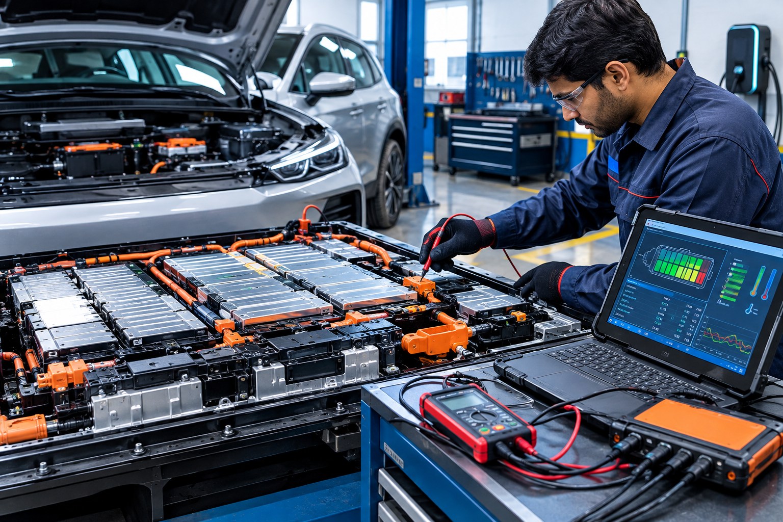
Electric Vehicle (EV) battery diagnostics is the process of checking the battery pack, individual cells, electrical connections, temperature sensors, insulation, voltage readings, and Battery Management System (BMS) to determine the actual condition of the battery.

The BMS is one of the most important electronic systems in an EV because it continuously monitors battery voltage, current, temperature, state of charge (SOC), and other operating parameters. When a battery-related fault occurs, proper diagnostics can help identify whether the problem is caused by a weak cell, sensor, wiring, communication issue, charging system, or the BMS itself.

Because EV battery packs can contain high-voltage electrical energy, diagnostic work should only be performed with the correct equipment, training, and manufacturer-approved safety procedures.

What Is EV Battery Diagnostics?

EV battery diagnostics involves measuring and analyzing different parameters of the high-voltage battery system.

A typical diagnostic process may include:

  • Battery pack voltage inspection
  • Individual cell or module voltage comparison
  • State of charge (SOC) analysis
  • State of health (SOH) evaluation
  • Battery temperature monitoring
  • Current measurement
  • Insulation resistance testing
  • BMS fault-code analysis
  • CAN communication diagnosis
  • Connector and wiring inspection
  • Charging and discharging performance evaluation

The objective is not simply to determine whether the battery works. A proper diagnostic procedure attempts to identify the specific reason for abnormal battery behavior.

Understanding the EV Battery Pack

An EV battery pack is normally made from multiple battery cells connected in series and parallel configurations.

Individual cells are grouped into modules, and multiple modules are combined to form the complete battery pack.

The battery system can therefore be viewed as:

Cell → Module → Battery Pack → BMS → Vehicle Control Systems

Depending on the vehicle design, the battery pack may also contain contactors, current sensors, temperature sensors, fuses, service disconnects, cooling components, and high-voltage connectors.

A problem in any of these components can affect vehicle performance.

What Is a Battery Management System (BMS)?

The Battery Management System is the electronic control system responsible for monitoring and managing the battery.

Its functions can include:

  • Monitoring cell voltages
  • Monitoring battery temperature
  • Measuring battery current
  • Calculating SOC
  • Estimating SOH
  • Detecting abnormal conditions
  • Controlling battery charging limits
  • Managing discharge limits
  • Controlling contactors
  • Protecting against overvoltage
  • Protecting against undervoltage
  • Protecting against excessive temperature
  • Communicating with other vehicle control modules

The exact BMS architecture varies between EV manufacturers and battery platforms.

Why BMS Testing Is Important

A battery pack can sometimes show a normal overall voltage while still having a problem with one or more cells.

For example, if most cells are operating within a similar voltage range but one cell group consistently behaves differently, the BMS may detect a cell imbalance or abnormal voltage condition.

BMS testing helps identify these differences.

It can also help determine whether a fault is related to:

  • Battery cells
  • Voltage sensing circuits
  • Temperature sensors
  • Current sensors
  • BMS communication
  • Wiring harnesses
  • Connectors
  • Contactors
  • Software or calibration
  • External charging systems

Important EV Battery Parameters

1. Cell Voltage

Cell voltage is one of the most important diagnostic parameters.

The BMS normally monitors individual cell groups or modules. During diagnosis, technicians compare the readings rather than relying only on total battery voltage.

A significant difference between cell-group readings may indicate:

  • Cell imbalance
  • A weak cell group
  • High internal resistance
  • Connection resistance
  • Measurement circuit problems

The acceptable voltage range depends on the battery chemistry, state of charge, temperature, and manufacturer specifications.

2. Battery Pack Voltage

Total pack voltage is measured by combining the voltage of the connected cell groups.

A diagnostic scan tool may display pack voltage electronically through the BMS.

If the measured voltage does not agree with the expected value, the cause may be related to the battery itself, voltage sensing, contactors, wiring, or measurement equipment.

3. State of Charge (SOC)

SOC represents the estimated amount of usable energy remaining in the battery.

It is similar to the fuel-level concept in a conventional vehicle, but the calculation is more complex.

The BMS can estimate SOC using information such as:

  • Battery current
  • Voltage
  • Temperature
  • Previous battery conditions
  • Charging and discharging history
  • Battery model calculations

SOC should not be interpreted as a direct measurement of battery health.

4. State of Health (SOH)

SOH provides an estimate of the battery’s remaining capacity or performance compared with its reference condition.

Battery aging can cause:

  • Reduced capacity
  • Increased internal resistance
  • Increased voltage variation under load
  • Reduced charging performance
  • Reduced driving range

SOH calculation methods differ between manufacturers and BMS designs.

Therefore, a scan-tool SOH value should be interpreted according to the vehicle manufacturer’s diagnostic procedures.

5. Battery Temperature

Temperature has a major effect on battery performance and safety.

The BMS monitors temperature sensors distributed throughout the battery system.

An abnormal temperature reading may indicate:

  • Sensor failure
  • Wiring problems
  • Cooling-system problems
  • Localized battery heating
  • Charging or operating conditions outside the expected range

Temperature readings should always be compared with the manufacturer’s specifications and with other sensors in the pack.

EV Battery Diagnostic Equipment

Professional EV diagnostics may require several types of equipment.

Diagnostic Scan Tool

A compatible diagnostic scanner can communicate with vehicle control modules and display:

  • BMS fault codes
  • Cell voltages
  • Battery temperatures
  • SOC
  • SOH
  • Pack current
  • Pack voltage
  • Contactor status
  • Charging-related parameters

A generic OBD scanner may not provide complete high-voltage battery information. Manufacturer-specific diagnostic equipment may be required.

Digital Multimeter

A suitable CAT-rated multimeter can be used for electrical measurements where permitted by the manufacturer’s service procedure.

The meter must be appropriate for the voltage category and measurement task.

Insulation Resistance Tester

An insulation tester can be used to evaluate electrical isolation between the high-voltage system and the vehicle chassis.

Insulation testing procedures vary by vehicle and battery architecture. Incorrect testing voltage or procedure can damage electronic components.

Current Measurement Equipment

Current sensors or appropriate measurement equipment can help evaluate battery charging and discharging behavior.

High-current measurements require equipment designed for the expected current and voltage.

Thermal Imaging Camera

A thermal camera can sometimes help identify abnormal heat patterns around:

  • Battery connections
  • Busbars
  • Contactors
  • Cables
  • Cooling components

Thermal inspection is an additional diagnostic method and does not replace electrical measurements or manufacturer procedures.

Step-by-Step EV Battery Diagnostic Process

Step 1: Follow High-Voltage Safety Procedures

Before any diagnostic work, identify the vehicle’s high-voltage system and follow the manufacturer’s shutdown and isolation procedure.

Do not assume that switching the vehicle off makes the battery system safe.

High-voltage batteries can retain dangerous energy even when the vehicle is not operating.

Use the required PPE, insulated tools, approved test equipment, and isolation procedures.

Step 2: Perform a Visual Inspection

Inspect the battery system for visible abnormalities.

Check for:

  • Damaged high-voltage cables
  • Corroded connectors
  • Loose connections
  • Physical battery damage
  • Signs of overheating
  • Coolant leakage
  • Water intrusion
  • Damaged wiring
  • Connector contamination

Do not continue testing if there is evidence of serious battery damage or another unsafe condition.

Step 3: Scan the BMS for Fault Codes

Connect the appropriate diagnostic tool and retrieve stored and active fault codes.

Do not immediately erase fault codes.

Record the codes and their associated data first.

Look for faults related to:

  • Cell voltage
  • Temperature
  • Insulation
  • Current sensing
  • Communication
  • Contactor operation
  • Charging
  • Battery management

The diagnostic code should be interpreted using the manufacturer’s service information.

Step 4: Check Cell Voltage Data

Review individual cell-group voltages through the diagnostic system if available.

Compare the readings under similar conditions.

A single abnormal reading does not automatically prove that the cell itself is defective. The sensing harness, connector, busbar, or BMS measurement circuit can also cause an abnormal reading.

Step 5: Compare Temperature Sensors

Review all available battery temperature readings.

Look for:

  • One sensor showing an unrealistic value
  • Significant temperature differences
  • Temperature increases during charging or load
  • Temperature-related BMS warnings

Sensor readings should be compared with ambient conditions and manufacturer specifications.

Step 6: Check Battery Current

Battery current information can help identify charging and discharging behavior.

Compare the BMS-reported current with the expected operating condition.

If the reading appears unrealistic, possible causes may include:

  • Current sensor problems
  • Wiring faults
  • Communication problems
  • BMS calculation issues

Step 7: Check BMS Communication

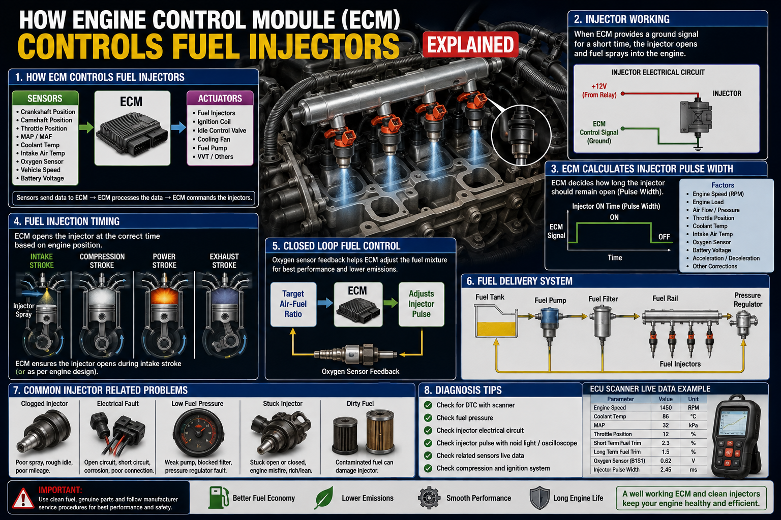
Modern EVs use communication networks such as CAN to exchange information between the BMS and other vehicle control modules.

Communication problems can produce symptoms such as:

  • Battery warning messages
  • Charging failure
  • Reduced power
  • Incorrect battery information
  • Vehicle not entering READY mode

A CAN-related fault does not necessarily mean that the BMS control unit itself is defective.

The wiring, connectors, power supply, ground, termination, or another control module may be responsible.

Step 8: Evaluate Insulation

High-voltage insulation is critical for vehicle safety.

The system must maintain adequate electrical isolation between high-voltage conductors and the vehicle chassis.

If an insulation fault is detected, possible causes can include:

  • Damaged cable insulation
  • Moisture
  • Coolant contamination
  • Battery casing problems
  • Component insulation failure
  • Charging-system faults

Use only the manufacturer’s specified test procedure because improper insulation testing can damage sensitive electronics.

Step 9: Check Contactors and Pre-Charge Operation

High-voltage battery packs commonly use contactors to connect and disconnect the battery from the vehicle’s high-voltage circuit.

A pre-charge circuit may also be used to control the initial charging of capacitors in the high-voltage system.

Faults in this area can cause:

  • No READY condition
  • Charging problems
  • High-voltage system shutdown
  • Contactor-related fault codes

Diagnosis should include the relevant BMS data and manufacturer test procedures.

How to Identify a Weak Battery Cell

A weak cell or cell group may not always be obvious when the battery is at rest.

A better diagnosis considers how the cell behaves during charging and discharging.

A potentially weak cell group may:

  • Drop in voltage faster under load
  • Reach the upper voltage limit earlier during charging
  • Show greater voltage deviation from other groups
  • Cause repeated BMS imbalance warnings
  • Contribute to reduced usable capacity

However, voltage variation alone is not enough to confirm a defective cell.

Battery temperature, SOC, current, internal resistance, and BMS calculations should also be considered.

Battery Cell Balancing

Cell balancing helps keep individual cell groups within an acceptable voltage relationship.

There are two common approaches:

Passive balancing: excess energy is dissipated as heat through balancing circuits.

Active balancing: energy can be transferred between cells or cell groups.

The actual balancing strategy depends on the BMS design.

If one cell group repeatedly becomes imbalanced, simply forcing a balance may not solve the underlying problem. The battery may have a degraded cell, increased resistance, or another electrical fault.

Common EV Battery and BMS Faults

Cell Voltage Imbalance

Possible causes include:

  • Cell aging
  • Capacity differences
  • High internal resistance
  • Poor connections
  • Cell sensing problems

Temperature Sensor Fault

Possible causes include:

  • Failed sensor
  • Damaged wiring
  • Connector problems
  • BMS input fault

Insulation Fault

Possible causes include:

  • Damaged insulation
  • Moisture
  • Coolant contamination
  • High-voltage component failure

BMS Communication Fault

Possible causes include:

  • CAN wiring problems
  • Poor connectors
  • Power supply issues
  • Ground problems
  • Network termination issues
  • Control-module failure

Charging Failure

Charging problems can originate from several systems, including:

  • BMS
  • On-board charger
  • Charging connector
  • High-voltage contactors
  • Temperature conditions
  • Battery protection logic
  • Communication between vehicle modules

A charging failure should therefore not automatically be blamed on the battery pack.

EV Battery Diagnostic Mistakes to Avoid

Several mistakes can create additional problems during EV diagnosis.

Do Not Measure High Voltage With Unsuitable Equipment

Always use equipment rated for the voltage and measurement category involved.

Do Not Ignore Isolation Procedures

A high-voltage battery must be treated as energized until the manufacturer’s isolation and verification procedure confirms otherwise.

Do Not Replace the BMS Without Diagnosis

Replacing an expensive BMS without proving that it is faulty can waste time and money.

Do Not Judge Battery Health From Pack Voltage Alone

A normal total voltage does not prove that every cell group is healthy.

Do Not Ignore Temperature Data

Temperature abnormalities can be an important clue to battery, cooling, sensor, or charging problems.

Battery Diagnostics During Charging

Charging is an important opportunity to observe battery behavior.

Depending on the vehicle and diagnostic equipment, technicians may monitor:

  • Charging current
  • Pack voltage
  • Cell voltage differences
  • Battery temperature
  • SOC
  • Charging power
  • Contactor status
  • BMS warnings

If one cell group behaves abnormally during charging, further diagnosis may be required.

Battery Diagnostics During Load

Battery behavior under load can reveal problems that may not appear during a static voltage check.

Under acceleration or another controlled load condition, a weak cell group may experience a larger voltage drop than healthier groups.

However, load testing on an EV must be performed according to the manufacturer’s procedure and appropriate safety requirements.

When Battery Replacement May Be Necessary

Battery replacement should not be the first conclusion after finding a battery-related fault.

Depending on the diagnosis, the repair may involve:

  • Wiring repair
  • Connector repair
  • Sensor replacement
  • Cooling-system repair
  • BMS-related repair
  • Cell or module replacement where supported
  • Contactor replacement
  • Charging-system repair

The battery pack may require replacement when the manufacturer determines that the pack or a major internal component has reached a condition where repair is not permitted or economically practical.

Importance of Manufacturer Service Information

EV battery systems are not identical.

Battery chemistry, voltage levels, BMS architecture, communication systems, cell configuration, cooling systems, diagnostic procedures, and allowable repair methods can differ substantially between vehicles.

For this reason, exact voltage limits, insulation limits, torque specifications, balancing procedures, isolation steps, and component replacement procedures should always come from the correct manufacturer service documentation.

EV Battery Diagnostics and Preventive Maintenance

Regular maintenance can help identify problems before they become severe.

Useful practices include:

  • Monitoring unusual charging behavior
  • Paying attention to battery warning messages
  • Keeping cooling systems maintained
  • Checking for physical damage
  • Inspecting charging equipment
  • Following recommended service intervals
  • Using appropriate diagnostic equipment when faults appear

Drivers should also avoid ignoring repeated battery warnings or unusual changes in charging performanceRead also how-to-change-bike-wheel-bearings

Conclusion

Electric Vehicle battery diagnostics and BMS testing require a systematic approach. Checking only the overall battery voltage is not enough to determine battery condition.

A proper diagnostic process evaluates cell-group voltage, temperature, current, SOC, SOH, insulation, BMS communication, contactors, charging behavior, and fault codes.

The most important principle is to diagnose the actual cause rather than replacing expensive battery components based only on symptoms.

Because EV battery packs operate at potentially hazardous high voltages, internal battery repair and high-voltage testing should be performed only by appropriately trained personnel using approved equipment and the vehicle manufacturer’s procedures.

Rajesh Technical Gyan

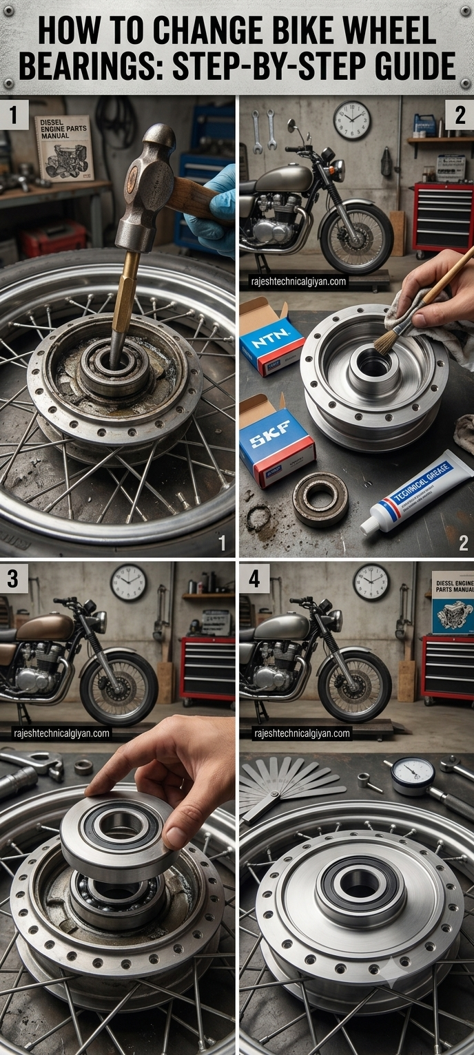
How to Change Bike Wheel Bearings: Step-by-Step Guide

Today, I will explain the step-by-step method for changing wheel bearings on a motorcycle or bike. Wheel bearings are small components, but they play a very important role in the safe and smooth operation of a motorcycle. They allow the wheels to rotate freely while supporting the load of the motorcycle, rider, passenger, and road forces.

A worn or damaged wheel bearing can cause wheel play, unusual noise, rough rotation, vibration, and poor handling. If the problem becomes severe and the bearing is ignored for a long time, it can affect other wheel components as well.

The good news is that wheel-bearing replacement is a repair that an experienced mechanic can perform with the correct tools and proper procedure.

However, the exact bearing size, number of bearings, spacer arrangement, torque specifications, and wheel-removal procedure can differ between motorcycles. Therefore, always check the service information for the exact bike before beginning the repair.

In this guide, I will explain the complete general procedure, from identifying a damaged bearing to removing the wheel, replacing the bearing, checking the spacers and seals, reinstalling the wheel, and performing the final safety inspection.


What Does a Wheel Bearing Do?

A motorcycle wheel bearing allows the wheel hub to rotate smoothly around the axle.

The bearing contains precision-machined races and rolling elements that reduce friction between the rotating wheel and the stationary axle or mounting components.

A properly functioning bearing helps the wheel rotate smoothly and contributes to stable handling.

Wheel bearings are designed to withstand:

  • Motorcycle weight
  • Rider weight
  • Braking forces
  • Acceleration forces
  • Cornering forces
  • Road impacts
  • Continuous wheel rotation

Because they operate under demanding conditions, wheel bearings eventually wear out.


Signs of a Bad Wheel Bearing

Before replacing a wheel bearing, it is important to identify the symptoms correctly.

Common signs include:

Rough Wheel Rotation

When the wheel is rotated by hand, a damaged bearing may feel rough rather than smooth.

Grinding or Humming Noise

A worn bearing can produce a humming, grinding, or rumbling sound.

Excessive Wheel Play

A damaged bearing may allow abnormal movement between the wheel and axle.

Vibration

Bearing wear can sometimes contribute to unusual vibration while riding.

Uneven Wheel Movement

The wheel may not rotate smoothly if the bearing is severely damaged.

However, these symptoms can also be caused by loose axle hardware, worn brake components, damaged tires, bent wheels, or other problems. A proper inspection is therefore important.


Tools Required

The exact tools depend on the motorcycle, but a typical wheel-bearing replacement may require:

  • Motorcycle stand or suitable lifting equipment
  • Socket set
  • Spanner set
  • Torque wrench
  • Screwdrivers
  • Allen keys
  • Circlip pliers if applicable
  • Bearing puller
  • Bearing driver or suitable press tools
  • Soft-faced hammer
  • Suitable drift or installation tool
  • Cleaning materials
  • Correct replacement bearings
  • New wheel seals where required

Using the correct bearing-removal and installation tools makes the job safer and reduces the risk of damaging the wheel hub.


Step 1: Identify the Correct Bearing

Before removing the wheel, identify the exact motorcycle model.

Check:

  • Motorcycle make
  • Model
  • Year
  • Wheel type
  • Front or rear wheel
  • Original bearing number
  • Bearing dimensions

Do not purchase a bearing simply because it looks similar to the old one.

The inner diameter, outer diameter, width, bearing type, and sealing arrangement must be correct.

If possible, confirm the part number using the manufacturer’s parts information.


Step 2: Secure the Motorcycle

Before removing a wheel, the motorcycle must be properly supported.

Use a suitable motorcycle stand or approved lifting equipment.

The motorcycle should be stable and should not be able to fall while the wheel is removed.

This is especially important when removing the front or rear wheel because the motorcycle’s balance can change significantly.

Never rely on an unstable object such as a brick, loose piece of wood, or improvised support.


Step 3: Remove the Wheel

The wheel-removal procedure depends on the motorcycle.

For a front wheel, components may include:

  • Axle
  • Axle nut
  • Brake caliper
  • Wheel spacers
  • Speed sensor or speedometer drive on some models

For a rear wheel, you may need to consider:

  • Rear axle
  • Brake caliper or bracket
  • Chain or belt drive
  • Wheel spacers
  • Sprocket carrier

Before removing anything, note the position of the spacers and other components.

Taking a photograph before disassembly can be very useful during reassembly.


Step 4: Remove Brake Components Carefully

If the brake caliper needs to be removed, support it properly.

Do not allow a brake caliper to hang from its hydraulic hose.

If the caliper is removed, secure it safely using an appropriate support.

Avoid squeezing the brake lever while the wheel or brake disc is removed unless the service procedure specifically requires it.

Keep the brake disc and pads free from oil, grease, and contamination.


Step 5: Remove the Axle

Remove the axle according to the motorcycle manufacturer’s procedure.

Keep all hardware and spacers organized.

Some motorcycles use different spacers on different sides of the wheel.

Mixing them up during reassembly can cause alignment or brake problems.

Once the axle is removed, carefully remove the wheel from the motorcycle.

Place the wheel on a clean work surface.


Step 6: Remove the Wheel Seals

Wheel bearings are commonly protected by seals.

Before removing the bearing, inspect the seals.

If the seals are damaged, hardened, cracked, or leaking, they should generally be replaced.

Remove the seal carefully without damaging the wheel hub or bearing seat.

Do not use excessive force against the machined surfaces of the wheel.


Step 7: Inspect the Wheel Spacer

Inside many motorcycle wheel hubs there is an internal spacer between the bearings.

This spacer is extremely important.

Before removing the bearings, note its position.

After the bearings are removed, inspect the spacer for:

  • Damage
  • Wear
  • Deformation
  • Corrosion
  • Incorrect length

Never discard the internal spacer.

It must be installed correctly during reassembly.


Step 8: Remove the Old Bearing

The old bearing can be removed using an appropriate bearing puller, blind-bearing puller, press, or other suitable workshop method.

The removal technique depends on the wheel design.

Avoid hitting the bearing directly with an unsuitable tool.

If a drift is used, it must be positioned correctly so that the bearing can be removed without damaging the hub.

Work evenly around the bearing where appropriate.

The goal is to remove the bearing without damaging the wheel’s bearing seat.


Step 9: Clean the Bearing Housing

Once the old bearing has been removed, thoroughly clean the bearing housing.

Remove:

  • Dirt
  • Old grease
  • Corrosion
  • Metal particles
  • Seal debris

Inspect the bearing seat carefully.

Look for:

  • Cracks
  • Scoring
  • Excessive wear
  • Corrosion
  • Damage
  • Signs that the old bearing had been spinning in the hub

If the bearing seat is damaged, simply installing a new bearing may not be a reliable repair.


Step 10: Inspect the Wheel Hub

Before installing the new bearing, inspect the entire wheel hub.

Check the bearing bores, internal spacer, axle area, brake disc mounting area, and other relevant components.

Also inspect the wheel itself for cracks, bends, or other damage.

If the wheel has suffered a major impact, it should be inspected carefully before being returned to service.


Step 11: Prepare the New Bearings

Compare the new bearings with the old ones.

Confirm:

  • Correct bearing number
  • Correct dimensions
  • Correct sealing arrangement
  • Correct quantity

Keep the new bearings clean.

Do not contaminate sealed bearings with dirt or unsuitable chemicals.

If the bearing manufacturer provides specific installation instructions, follow them.


Step 12: Install the New Bearing

Bearing installation requires care.

The new bearing should be pressed or driven into the hub using an appropriate bearing driver or press.

The installation force must be applied to the correct bearing race.

When installing a bearing onto a shaft, force is generally applied to the inner race.

When installing a bearing into a housing, force is generally applied to the outer race.

Never unnecessarily transfer installation force through the rolling elements.

Improper installation can damage a brand-new bearing before the motorcycle is even ridden.


Step 13: Install the Internal Spacer

After the first bearing is installed, make sure the internal wheel spacer is correctly positioned.

The spacer sits between the wheel bearings on many motorcycle designs.

Its purpose is to maintain the correct relationship between the bearings when the axle is tightened.

Do not omit this component.

Do not replace it with an improvised spacer.

The correct spacer length and design are important for proper wheel assembly.


Step 14: Install the Second Bearing

Install the second bearing carefully.

Again, use the appropriate bearing installation method.

Do not drive the bearing deeper than the manufacturer’s intended seating position.

The bearing must be properly seated while the internal spacer remains correctly positioned.

If the spacer becomes trapped incorrectly or is forced into the wrong position, the wheel may not rotate properly after the axle is tightened.


Step 15: Install New Wheel Seals

Install the correct wheel seals after the bearings are properly seated.

The sealing lip should face the correct direction according to the manufacturer’s design.

Apply a suitable lubricant to the seal lip if specified.

Press the seal into position evenly.

Do not hammer directly against the seal lip.

A damaged seal can allow water and dirt to enter the bearing area, shortening bearing life.


Step 16: Check the Wheel by Hand

Before reinstalling the wheel, rotate it by hand.

The wheel should rotate smoothly.

Listen for:

  • Grinding
  • Clicking
  • Roughness
  • Binding

Also check for abnormal play.

If the wheel does not rotate correctly, stop and inspect the bearing installation and spacer arrangement.

Do not proceed until the problem has been identified.


Step 17: Reinstall the Wheel

Place the wheel back into position.

Install the spacers exactly as they were designed.

Insert the axle carefully.

Do not force the axle through a misaligned assembly.

If the axle does not enter easily, check wheel alignment, spacer position, and fork or swingarm alignment.


Step 18: Reinstall Brake Components

Reinstall the brake caliper or other brake components according to the manufacturer’s procedure.

Make sure:

  • Brake disc is correctly positioned
  • Caliper is correctly mounted
  • Fasteners are correctly installed
  • Brake components are free from oil and grease

Use the manufacturer’s specified torque values for critical fasteners.

A torque wrench is strongly recommended for axle and brake-related fasteners.


Step 19: Tighten the Axle Correctly

The axle and related fasteners must be tightened according to the motorcycle manufacturer’s specified sequence and torque.

Do not guess the torque value.

Incorrect axle tightening can create serious handling or bearing problems.

After tightening, verify that the wheel rotates normally.

On some motorcycles, the correct procedure includes a specific sequence for axle and pinch-bolt tightening. Follow the exact procedure for the model being serviced.


Step 20: Check Brake Operation

Before riding the motorcycle, operate the brake lever or pedal several times as appropriate.

This is particularly important if a brake caliper was removed.

Confirm that normal brake pressure and lever feel have returned.

Never ride away without confirming that the brakes are functioning correctly.


Step 21: Check Wheel Play

With the motorcycle safely supported, check for abnormal wheel movement.

The wheel should not have excessive looseness.

If abnormal play remains after installing new bearings, investigate:

  • Bearing seating
  • Internal spacer
  • Axle
  • Wheel hub
  • Axle hardware
  • Other related components

Do not assume that a new bearing automatically means the wheel is safe.


Step 22: Perform a Final Inspection

Before the first test ride, inspect everything carefully.

Check:

  • Axle
  • Axle nut
  • Pinch bolts where applicable
  • Wheel spacers
  • Brake caliper
  • Brake disc
  • Brake operation
  • Wheel rotation
  • Tire condition
  • Wheel alignment
  • Chain adjustment on rear-wheel-drive motorcycles
  • Any removed electrical sensor or speed sensor

Make sure no tools or loose components remain around the motorcycle.


Step 23: Perform a Careful Test Ride

The first test ride should be short and controlled.

Do not immediately ride at high speed.

Start at low speed in a safe area and check:

  • Steering feel
  • Wheel rotation
  • Brake operation
  • Vibration
  • Unusual noise
  • Stability

If anything feels abnormal, stop and inspect the motorcycle again.


Common Mistakes When Changing Wheel Bearings

Using the Wrong Bearing

A bearing that appears similar may have different dimensions or specifications.

Always confirm the correct part.

Hammering Directly on the Bearing

Improper impact can damage the bearing races and rolling elements.

Installing the Bearing at the Wrong Depth

The bearing must be seated according to the correct hub design.

Forgetting the Internal Spacer

The internal spacer is an important part of many motorcycle wheel assemblies.

Installing the Spacers on the Wrong Sides

Incorrect spacer placement can affect wheel alignment and brake positioning.

Reusing Damaged Seals

Old or damaged seals can allow contamination into the new bearing.

Guessing Axle Torque

Use the manufacturer’s specified torque and tightening procedure.

Contaminating the Brake Disc

Oil or grease on the brake disc can seriously reduce braking performance.

Riding Without Checking the Brakes

Always restore and verify brake operation before riding.


How to Make Wheel Bearings Last Longer

Wheel-bearing life can be improved through proper maintenance and inspection.

Avoid pressure-washing directly at wheel seals.

Keep the axle and wheel components clean during service.

Inspect bearings when unusual noise or play appears.

Replace damaged seals promptly.

Avoid ignoring water or dirt contamination.

During tire replacement or wheel service, take the opportunity to inspect the bearings.

If a motorcycle frequently operates in rain, mud, water, or dusty conditions, more frequent inspection may be appropriate.


Front and Rear Wheel Bearing Differences

The basic replacement principle is similar, but front and rear wheels can have different arrangements.

The rear wheel may include additional components such as:

  • Sprocket carrier
  • Cush-drive components
  • Multiple spacers
  • Brake disc
  • Chain-related components

The front wheel may include:

  • Brake disc
  • Speed sensor
  • Different wheel spacers
  • ABS components on equipped motorcycles

Therefore, never assume that every motorcycle wheel is assembled in exactly the same way.


ABS Motorcycle Considerations

Modern motorcycles may have ABS sensors and tone rings near the wheel.

Extra care is required when removing and reinstalling wheels.

Do not damage:

  • ABS sensor
  • Sensor wiring
  • Tone ring
  • Sensor mounting bracket

Keep the correct sensor gap according to the manufacturer’s specifications.

If an ABS warning light appears after wheel installation, the system should be diagnosed before normal riding.Read also 10-hp-diesel-engine-generator-set


Final Thoughts

Changing a motorcycle wheel bearing is an important maintenance and repair procedure, but it should never be treated as a simple parts-replacement job.

The bearing, wheel hub, internal spacer, axle, seals, brake components, and related parts all work together.

The most important steps are to identify the correct bearing, support the motorcycle safely, remove the wheel carefully, inspect the hub, install the bearing using the correct method, position the internal spacer correctly, replace damaged seals, and tighten the axle and related fasteners to the manufacturer’s specifications.

Always remember that motorcycle wheel and brake components are safety-critical. If you do not have the correct tools, lifting equipment, measurement equipment, or experience, it is safer to have the work performed by a qualified motorcycle technician.

After the repair, never skip the final inspection. Check wheel rotation, wheel play, brake operation, axle installation, and alignment before riding.

A correctly installed wheel bearing can help restore smooth wheel rotation and reliable motorcycle handling. Regular inspection can also help identify bearing wear before it becomes a more serious problem.

I hope this complete guide helps motorcycle owners, mechanics, workshop technicians, and DIY enthusiasts understand the correct general procedure for changing bike wheel bearings.

For more practical motorcycle repair guides, engine troubleshooting, maintenance tips, and professional workshop knowledge, keep visiting Rajesh Technical Gyan.

clear & Easy 10 HP Diesel Generator Care Guide

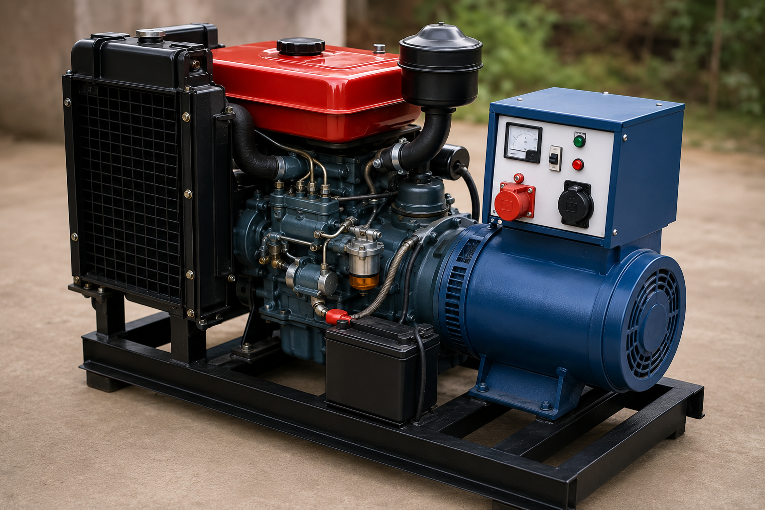
A diesel generator set, commonly known as a diesel genset, combines a diesel engine with an electrical generator to produce electricity. A 10 HP diesel engine can be used in a variety of applications depending on the engine design, generator efficiency, operating speed, and alternator rating.

From agricultural farms and workshops to small businesses, construction sites, rural locations, backup power systems, and remote work areas, diesel generator sets can provide valuable electrical power when the main electricity supply is unavailable or unreliable.

However, horsepower alone does not determine the electrical output of a generator. The actual generator capacity must be identified from the alternator rating, normally expressed in kW or kVA, along with the engine’s rated speed and operating specifications.

In this guide, I will explain how a 10 HP diesel generator set works, its major components, starting system, fuel system, cooling system, lubrication, electrical generation, maintenance requirements, common problems, and practical troubleshooting methods.


What Is a 10 HP Diesel Generator Set?

A 10 HP diesel generator set is a compact power-generation system built around a diesel engine and an electrical alternator.

The diesel engine provides mechanical power.

The alternator converts that mechanical power into electrical energy.

In simple terms:

Diesel fuel → Engine combustion → Mechanical rotation → Alternator → Electrical power

The complete generator set may also include a fuel tank, control panel, battery, cooling system, exhaust system, mounting frame, protective covers, and various safety devices.

The exact design depends on the manufacturer and application.


How Does a Diesel Generator Work?

The diesel engine burns fuel inside its cylinders.

During combustion, expanding gases push the piston downward.

The connecting rod transfers this movement to the crankshaft.

The crankshaft converts the reciprocating movement of the piston into rotary motion.

The rotating crankshaft drives the alternator.

Inside the alternator, mechanical rotation produces electrical energy through electromagnetic induction.

The generated electricity is then delivered through the generator’s output terminals to the connected electrical load.

This entire process happens continuously while the generator is running.


Major Components of a 10 HP Diesel Generator

A typical diesel generator set contains several important systems.

Diesel Engine

The engine is the prime mover.

Alternator

The alternator converts mechanical energy into electrical energy.

Fuel System

The fuel system stores, filters, and supplies diesel to the injection system.

Lubrication System

Engine oil reduces friction and helps remove heat from moving components.

Cooling System

The cooling system controls engine temperature.

Air Intake System

The engine requires clean air for combustion.

Exhaust System

The exhaust system safely carries combustion gases away from the engine.

Battery and Starting System

The battery and starter system provide the energy required to start the engine on electrically started models.

Control Panel

The control panel allows the operator to monitor and control the generator.

Fuel Tank

The fuel tank stores diesel for engine operation.


Understanding the 10 HP Rating

One important point often causes confusion.

10 HP refers to engine power, not directly to generator electrical output.

The electrical output depends on several factors, including:

  • Engine rated speed
  • Alternator efficiency
  • Generator design
  • Power factor
  • Continuous or standby rating
  • Manufacturer specifications

Therefore, a 10 HP diesel engine should not automatically be assumed to produce a specific kVA or kW rating.

Always check the generator nameplate for the actual electrical output.

The nameplate may provide information such as:

  • Rated voltage
  • Rated current
  • Frequency
  • Rated speed
  • kW
  • kVA
  • Phase
  • Power factor

Diesel Fuel System

The fuel system is critical for reliable engine operation.

Fuel normally travels from the tank through the fuel filter toward the injection system.

The injection system delivers fuel into the combustion chamber at the required time and pressure.

Important fuel-system components may include:

  • Fuel tank
  • Fuel filter
  • Fuel lines
  • Injection pump
  • Injector
  • Fuel-return system

Dirty fuel or a restricted filter can reduce engine performance.

Water contamination in diesel fuel can also cause serious fuel-system problems.

Regular fuel-filter inspection and replacement should therefore be part of preventive maintenance.


Air Intake System

A diesel engine requires a large amount of clean air.

The air filter prevents dust and other contaminants from entering the engine.

If the air filter becomes heavily restricted, the engine may experience:

  • Poor acceleration
  • Black smoke
  • Reduced power
  • Increased fuel consumption
  • Difficult operation under load

A generator operating in a dusty agricultural or construction environment may require more frequent air-filter inspection.

Always follow the engine manufacturer’s recommended cleaning or replacement procedure.


Diesel Injection System

The injection system controls the delivery of diesel fuel into the engine.

The injection timing and quantity are extremely important.

If fuel injection is incorrect, the engine may produce:

  • Excessive smoke
  • Hard starting
  • Poor power
  • Rough running
  • Increased fuel consumption
  • Abnormal combustion noise

Fuel injection components operate under high pressure.

For this reason, never place your hands near a suspected high-pressure fuel leak while the engine is operating.

High-pressure fuel can penetrate skin and cause serious injury.

Fuel-system repairs should be performed using the correct equipment and procedure.


Lubrication System

Engine oil is essential for protecting the internal components.

The oil lubricates components such as:

  • Crankshaft bearings
  • Connecting-rod components
  • Piston and cylinder surfaces
  • Camshaft components
  • Other moving parts

Engine oil also helps carry heat away from certain internal components and transports contaminants toward the filtration system where applicable.

Always use the oil grade and specification recommended for the exact engine.

Do not judge oil condition only by its color.

The correct service interval should be based on the manufacturer’s recommendations and operating conditions.


Cooling System

A diesel engine produces considerable heat during combustion.

The cooling system keeps the engine within its intended operating temperature range.

Depending on the engine design, cooling may be provided by air or liquid coolant.

For liquid-cooled systems, important components may include:

  • Radiator
  • Coolant
  • Water pump
  • Thermostat
  • Cooling fan
  • Hoses

For air-cooled engines, cooling fins must remain clean and unobstructed.

Excessive dirt around cooling fins can restrict airflow and contribute to overheating.


Exhaust System

The exhaust system carries combustion gases away from the engine.

A diesel generator should always be operated in a properly ventilated area.

Never operate a diesel generator inside a closed room, home, garage, or other enclosed space unless it is specifically designed and installed for that environment with appropriate exhaust and ventilation systems.

Diesel exhaust contains hazardous gases, including carbon monoxide.

A generator should be positioned outdoors and away from doors, windows, and air-intake openings according to applicable safety guidance.


Starting a 10 HP Diesel Generator

The starting procedure depends on the exact engine.

An electric-start diesel generator may use:

  1. Battery
  2. Starter motor
  3. Ignition or control switch
  4. Fuel system
  5. Engine controls

Before starting:

  • Check engine oil
  • Check fuel level
  • Inspect for leaks
  • Check battery connections
  • Make sure the generator is positioned safely
  • Disconnect unnecessary electrical loads
  • Ensure adequate ventilation

After starting, allow the engine to stabilize before applying significant electrical load.

Always follow the manufacturer’s starting instructions.


Generator Alternator

The alternator is responsible for producing electrical energy.

The alternator contains electromagnetic components that work together to generate electricity as the engine rotates the alternator shaft.

The generated output depends on the alternator’s design and operating speed.

A generator intended for a particular frequency must operate at the correct rated speed.

For example, generator frequency is related to rotational speed and the number of electrical poles in the alternator.

This is why incorrect engine speed can affect electrical frequency.


Why Engine Speed Matters

Engine speed is extremely important in a generator set.

If the engine runs too slowly or too quickly, the generator’s electrical output may not remain within its intended operating range.

Incorrect speed can affect:

  • Frequency
  • Voltage regulation
  • Connected electrical equipment
  • Engine performance
  • Fuel consumption

Never increase engine speed simply to obtain more electrical power.

The engine and alternator are designed to operate within specified limits.


Generator Load Management

A generator should not be overloaded.

Before connecting equipment, calculate the expected electrical load.

Consider equipment such as:

  • Pumps
  • Motors
  • Lights
  • Fans
  • Refrigerators
  • Workshop machines
  • Agricultural equipment
  • Electronic devices

Motors can require significantly more current during startup than during normal running.

Therefore, starting loads must also be considered.

Always keep the connected load within the generator’s rated capacity.


Preventive Maintenance

Regular maintenance is the key to long generator life.

A basic maintenance routine may include:

Engine Oil

Check the oil level regularly and replace the oil at the recommended interval.

Air Filter

Inspect and clean or replace it according to the manufacturer’s instructions.

Fuel Filter

Replace the fuel filter at the specified service interval.

Fuel System

Inspect fuel lines and connections for leaks.

Cooling System

Keep cooling passages clean and check coolant where applicable.

Battery

Inspect terminals and battery condition on electric-start systems.

Electrical Connections

Check for loose or damaged connections.

Belts

Inspect accessible drive belts for wear or damage where applicable.

Exhaust

Check for leaks, damage, or excessive soot.


Daily Inspection Checklist

Before starting the generator, perform a quick inspection.

Check:

  • Engine oil level
  • Diesel level
  • Fuel leakage
  • Oil leakage
  • Coolant level where applicable
  • Air filter condition
  • Battery connections
  • Electrical cables
  • Exhaust system
  • Engine mounting
  • Control panel indicators

A few minutes of inspection can help identify problems before they become major failures.


Common Problem: Diesel Engine Does Not Start

If the engine does not start, begin with basic checks.

Check Fuel

Make sure sufficient clean diesel is available.

Check Fuel Supply

Inspect the fuel line, filter, and injection-system supply.

Check Battery

A weak battery may not turn the starter sufficiently fast.

Check Engine Oil

Some engines have safety systems that can prevent starting when oil level or oil-pressure conditions are abnormal.

Check Air Supply

A severely restricted air filter can affect combustion.

Check Controls

Make sure the stop/run control is in the correct position.

If the engine still does not start, further diagnosis may require fuel-system and compression testing.


Common Problem: Generator Produces Black Smoke

Black smoke generally indicates incomplete combustion or excessive fuel relative to available air, although diagnosis depends on the engine.

Possible causes include:

  • Restricted air filter
  • Excessive engine load
  • Fuel-system problems
  • Incorrect injection condition
  • Poor combustion
  • Engine wear

Start with simple checks before replacing expensive components.


Common Problem: Generator Overheats

Possible causes can include:

  • Low coolant
  • Blocked radiator
  • Dirty cooling fins
  • Cooling fan problems
  • Excessive load
  • Low engine oil
  • Poor airflow
  • Internal engine problems

Never open a hot pressurized cooling system.

Allow the engine to cool before inspection.


Common Problem: Low Electrical Output

If the generator runs but electrical output is lower than expected, possible causes can include:

  • Excessive load
  • Incorrect engine speed
  • Alternator problem
  • Voltage-regulation problem
  • Wiring issue
  • Poor electrical connection
  • Mechanical drive problem

Measure voltage and frequency using appropriate equipment.

Electrical testing should be performed by someone who understands the risks associated with generator output.


Common Problem: Excessive Vibration

Vibration can originate from either the engine or generator assembly.

Possible causes include:

  • Loose mounting bolts
  • Damaged engine mounts
  • Misalignment
  • Mechanical imbalance
  • Crankshaft problems
  • Bearing wear
  • Alternator problems

Do not ignore a sudden increase in vibration.

Continuing operation can damage mounting components and other parts.


Fuel Efficiency Tips

Good maintenance can help maintain efficient operation.

Keep the Air Filter Clean

A restricted air filter can reduce engine efficiency.

Maintain the Correct Engine Oil

Use the recommended oil and service interval.

Avoid Unnecessary Overloading

Operate the generator within its rated capacity.

Maintain the Fuel System

Use clean fuel and replace filters as required.

Keep the Engine Properly Cooled

Overheating can reduce performance and reliability.

Avoid Extended Unnecessary Idling

Follow the manufacturer’s recommendations for operating and warm-up periods.


Safety Rules for Diesel Generators

Safety should always come before convenience.

Never operate a portable diesel generator in an enclosed space.

Keep the generator away from combustible materials.

Do not touch exposed electrical terminals.

Keep children and untrained people away from the running generator.

Never refuel a hot or running engine unless the manufacturer’s procedure specifically allows it; as a general safety practice, shut the engine down and allow it to cool before refueling.

Keep fuel away from flames and sparks.

Use correctly rated electrical cables and protective devices.

If connecting a generator to a building electrical system, use a properly designed and installed transfer arrangement. Never back-feed a building through a wall outlet.

Electrical installation and generator connection should comply with applicable local regulations and be performed by a qualified professional where required.


How to Increase Generator Life

The best way to extend generator life is not to modify the engine unnecessarily.

Instead:

  • Follow the service schedule
  • Use correct lubricants
  • Maintain clean fuel
  • Keep filters in good condition
  • Avoid overloading
  • Monitor engine temperature
  • Check oil regularly
  • Inspect electrical connections
  • Store the generator correctly
  • Repair small problems early

Preventive maintenance is usually much cheaper than repairing a severely damaged engine or alternator.


Long-Term Storage

If the generator will not be used for an extended period, prepare it according to the manufacturer’s storage instructions.

Depending on the engine and fuel system, this may include:

  • Cleaning the generator
  • Changing oil if required
  • Managing fuel appropriately
  • Protecting against moisture
  • Checking the battery
  • Covering the unit while allowing appropriate ventilation
  • Storing it in a dry and secure location

Do not simply leave a generator unused for months without preparation.


Diesel Generator for Agricultural and Workshop Use

A compact diesel generator can be useful for applications where electrical power is required away from the main grid.

Possible applications include:

  • Agricultural farms
  • Water-pump systems
  • Small workshops
  • Construction areas
  • Rural businesses
  • Temporary work sites
  • Emergency backup applications

However, the generator must always be selected according to the actual electrical load rather than engine horsepower alone.


10 HP Diesel Generator Buying Guide

If you are planning to purchase a 10 HP diesel generator set, do not look only at the engine.

Check the complete specification.

Important factors include:

  • Engine manufacturer
  • Engine model
  • Rated engine speed
  • Alternator rating
  • Rated kW
  • Rated kVA
  • Voltage
  • Frequency
  • Phase
  • Fuel consumption
  • Cooling system
  • Starting system
  • Fuel-tank capacity
  • Noise level
  • Warranty
  • Availability of spare parts
  • Local service support

A generator with easily available parts and technical support can be more practical over the long term.


Frequently Asked Questions

Can a 10 HP diesel engine run a generator?

Yes, a diesel engine can be used to drive an alternator, but the actual electrical output depends on the engine’s rated power, operating speed, alternator efficiency, and generator design.

Does 10 HP mean 10 kW?

No.

Horsepower and electrical kilowatts are different ratings. A 10 HP engine should not automatically be considered a 10 kW generator.

How often should a diesel generator be serviced?

The correct service interval depends on the specific engine and manufacturer. Always follow the recommended operating-hour or calendar-based schedule.

Why is my diesel generator producing black smoke?

Possible causes include excessive load, restricted air intake, fuel-system problems, or poor combustion. Start with basic inspection before replacing components.

Can a generator run continuously?

Some generator sets are designed for continuous-duty applications while others are intended for standby use. Always follow the manufacturer’s duty rating and operating limits.

Can I connect a generator directly to my house?

A generator should not be connected to a building by unsafe back-feeding methods. A properly designed transfer system and suitable protection are required, with installation performed according to local electrical regulations.Read also 10hp-engine-crankshaft-bearing-replacement


Final Thoughts

A 10 HP Diesel Engine Generator Set can be a valuable source of electrical power for farms, workshops, rural locations, construction sites, small businesses, and backup applications.

But the most important thing to understand is that engine horsepower does not directly equal generator electrical capacity.

The engine provides mechanical power, while the alternator converts that mechanical power into electricity. The final output depends on the complete generator-set design.

For reliable performance, pay attention to fuel quality, engine oil, air filtration, cooling, engine speed, electrical load, battery condition, and regular preventive maintenance.

Never overload the generator and never ignore abnormal smoke, vibration, overheating, oil leakage, or unusual mechanical noise.

Most importantly, operate diesel generators outdoors or in properly engineered environments where exhaust gases can be safely managed, and follow all electrical and fuel-safety requirements.

A well-maintained generator can provide dependable service for many years, but reliability begins with correct selection, proper installation, responsible operation, and regular maintenance.

I hope this complete guide to the 10 HP Diesel Engine Generator Set helps mechanics, farmers, workshop owners, technicians, generator operators, and DIY enthusiasts understand how these machines work and how to maintain them properly.

For more practical diesel engine repair, generator maintenance, motorcycle repair, automotive troubleshooting, and mechanical workshop guides, keep visiting Rajesh Technical Giyan

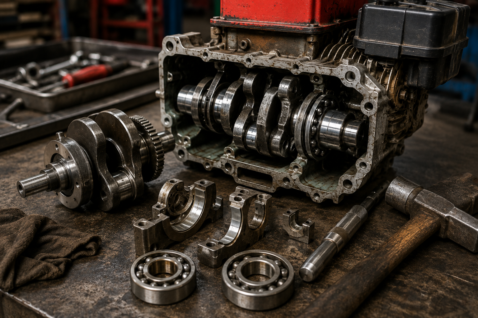
How to Replace Crankshaft Bearing in a 10 HP Engine: Complete Step-by-Step Guide

The crankshaft bearing is one of the most important components inside an engine. It supports the crankshaft and allows it to rotate smoothly while carrying the loads generated during engine operation. When a crankshaft bearing becomes worn or damaged, the engine may develop abnormal noise, excessive vibration, crankshaft play, overheating, or poor mechanical performance.

A damaged bearing should not be ignored. Continued operation can damage the crankshaft, bearing housing, connecting rod, seals, and other internal engine components.

The exact design of a 10 HP engine can vary depending on the manufacturer and application. Some engines use different bearing arrangements, crankcase designs, lubrication systems, and shaft configurations. Therefore, the exact bearing number, dimensions, clearances, torque specifications, and assembly procedure must always be confirmed for the particular engine being repaired.

This guide explains the general workshop procedure for replacing a crankshaft bearing safely and correctly.


1. Identify the Engine and Bearing

Before opening the engine, identify the exact engine model and specification.

A “10 HP engine” describes the approximate power output, but it does not identify the exact engine design.

Check:

  • Engine manufacturer
  • Model number
  • Engine serial number
  • Crankshaft design
  • Bearing type
  • Bearing dimensions
  • Lubrication system
  • Recommended replacement parts

Never order a bearing based only on horsepower.

The correct bearing must match the original engine specification.


2. Recognize the Symptoms of a Bad Crankshaft Bearing

A damaged crankshaft bearing can produce several symptoms.

Common signs include:

  • Deep knocking or rumbling noise
  • Excessive engine vibration
  • Crankshaft side play
  • Abnormal bearing noise
  • Difficult engine rotation
  • Excessive heat
  • Metal particles in engine oil
  • Oil leakage around a damaged seal
  • Reduced engine performance

However, these symptoms can also be caused by other mechanical problems.

Therefore, the bearing should be inspected before replacing it.


3. Prepare the Required Tools

Before starting the repair, prepare the necessary tools.

Typical tools may include:

  • Socket set
  • Spanner set
  • Screwdrivers
  • Allen keys where applicable
  • Torque wrench
  • Bearing puller
  • Bearing separator if required
  • Soft-faced hammer
  • Circlip pliers
  • Feeler gauge
  • Vernier caliper
  • Micrometer
  • Cleaning brush
  • Engine-safe cleaning solvent
  • Assembly lubricant
  • Suitable heating equipment if specified
  • New gaskets and seals
  • Correct replacement bearing

For some engines, a hydraulic press may be required.

Do not try to remove a tightly fitted bearing by repeatedly striking the crankshaft with a normal steel hammer.


4. Clean the Engine Before Disassembly

Before opening the engine, clean the outside thoroughly.

Dirt and dust around the crankcase can enter the engine during disassembly.

Clean the:

  • Crankcase exterior
  • Cylinder area
  • Bearing housing area
  • Oil-drain area
  • Shaft area
  • Fasteners

A clean working environment is extremely important during engine rebuilding.


5. Drain the Engine Oil

If the engine uses a wet-sump lubrication system, drain the engine oil before disassembly.

Place an appropriate drain container underneath the drain point.

Remove the drain plug carefully and allow the oil to drain completely.

Inspect the drained oil for unusual metal particles.

Metallic debris can provide useful information about internal engine wear.

Dispose of used oil responsibly.


6. Remove External Components

Depending on the engine design, several external components may need to be removed before accessing the crankcase.

These can include:

  • Recoil starter or electric starter components
  • Fuel tank
  • Exhaust components
  • Carburetor
  • Air filter assembly
  • Flywheel
  • Ignition components
  • Pulley or coupling
  • Side covers
  • Oil pump components
  • Other external brackets

Before removing components, take photographs or make reference marks where useful.

This can make reassembly easier.


7. Remove the Flywheel Carefully

Many small engines use a flywheel mounted on the crankshaft.

The flywheel may be secured with a nut, washer, key, or other retaining arrangement.

Remove the retaining hardware and use the appropriate flywheel puller if necessary.

Do not strike the outer edge of the flywheel aggressively.

Also inspect the flywheel key.

A damaged or incorrectly installed key can cause ignition timing problems on engines where the key establishes the required position.


8. Remove the Crankcase Components

Once the external components are removed, access the crankcase according to the engine’s design.

Remove the crankcase fasteners in an appropriate sequence.

Keep bolts organized because different fasteners may have different lengths.

If the crankcase halves are joined tightly, use the manufacturer’s recommended separation points.

Do not force a screwdriver between precision-machined mating surfaces because this can damage the sealing surfaces.


9. Separate the Crankcase Carefully

Once all fasteners and retaining components have been removed, separate the crankcase carefully.

Inspect the mating surfaces for:

  • Old gasket material
  • Sealant
  • Scratches
  • Cracks
  • Warping
  • Corrosion

Do not use excessive force.

If the crankcase refuses to separate, stop and check whether a hidden fastener, circlip, bearing retainer, or other component is still installed.


10. Remove the Crankshaft

After opening the crankcase, carefully remove the crankshaft assembly.

Depending on the engine design, the crankshaft may be connected to the piston and connecting rod.

Do not allow the crankshaft to fall or contact hard surfaces.

Place it on a clean workbench.

Inspect the crankshaft for:

  • Scoring
  • Wear
  • Blue or dark heat marks
  • Damaged bearing journals
  • Excessive play
  • Thread damage
  • Keyway damage

A new bearing should not be installed onto a severely damaged crankshaft journal.


11. Inspect the Old Bearing

Before removing the old bearing, inspect it carefully.

Check for:

  • Rough rotation
  • Excessive play
  • Noise
  • Discoloration
  • Pitting
  • Damaged seals
  • Corrosion
  • Spinning in the housing

A healthy bearing should rotate smoothly without abnormal roughness.

If the bearing feels gritty, loose, noisy, or damaged, replacement is usually required.


12. Remove the Old Bearing

The correct removal method depends on the bearing arrangement.

If the bearing is mounted on the crankshaft, an appropriate bearing puller or separator may be required.

If the bearing is installed inside the crankcase housing, the appropriate removal tool should be used from the correct direction.

Never apply force to the wrong bearing race.

For example, when removing a bearing from a shaft, force should be applied appropriately to the race that is fitted to the shaft.

Incorrect force can damage the bearing seat or crankshaft.


13. Inspect the Bearing Housing

After removing the old bearing, clean the bearing housing thoroughly.

Inspect the housing for:

  • Cracks
  • Wear
  • Scoring
  • Corrosion
  • Loose bearing fit
  • Damage to retaining features

The bearing must fit correctly in the housing.

If the bearing housing has become excessively loose, simply installing a new bearing may not solve the problem.

The crankcase may require further repair or replacement.


14. Inspect the Crankshaft Journal

The crankshaft should be inspected before installing the new bearing.

Measure the relevant shaft dimensions using appropriate precision measuring equipment.

Check for:

  • Wear
  • Taper
  • Out-of-round condition
  • Scoring
  • Corrosion
  • Heat damage

Compare the measurements with the manufacturer’s service limits.

If the crankshaft is outside the permitted specification, replacing only the bearing may result in another failure.


15. Select the Correct Replacement Bearing

The replacement bearing must match the exact engine specification.

Check:

  • Bearing number
  • Inside diameter
  • Outside diameter
  • Width
  • Clearance specification
  • Seal configuration
  • Temperature rating
  • Lubrication requirements

Do not choose a bearing only because its dimensions appear similar.

The correct bearing specification is important for reliable engine operation.


16. Prepare the New Bearing

Before installation, inspect the new bearing.

Make sure:

  • It is clean
  • It is undamaged
  • The correct bearing is being used
  • The seals are in good condition where applicable
  • It has not been contaminated by dirt

Do not wash a sealed bearing with an unsuitable solvent.

Follow the bearing manufacturer’s recommendations.


17. Install the New Bearing

Bearing installation requires care.

Depending on the engine design, the bearing may be installed using a press, suitable installation tool, or controlled heating method.

The force must be applied to the correct bearing race.

Never transfer installation force through the rolling elements unnecessarily.

If the bearing is being pressed onto a shaft, apply force appropriately to the inner race.

If the bearing is being pressed into a housing, apply force appropriately to the outer race.

This prevents damage to the new bearing.


18. Use Controlled Heating When Appropriate

Some bearing installations are designed to use controlled heating to expand the bearing slightly before installation.

If this method is specified, use appropriate temperature-controlled equipment.

Do not heat a bearing with an uncontrolled flame.

Excessive heat can damage bearing lubrication, seals, or material properties.

Always follow the bearing manufacturer’s and engine manufacturer’s installation instructions.


19. Install the Bearing to the Correct Position

The bearing must be fully and correctly seated.

After installation, check that:

  • The bearing is fully seated
  • Retaining clips are correctly installed
  • Bearing orientation is correct
  • The crankshaft rotates correctly
  • No abnormal resistance exists

Do not assume that a bearing is correctly installed simply because it looks close to its final position.


20. Replace the Oil Seals

Whenever the crankshaft and bearing assembly is being rebuilt, inspect the oil seals.

If a seal is worn, hardened, damaged, or leaking, replace it with the correct seal.

A new bearing will not solve an oil leak caused by a damaged crankshaft seal.

When installing an oil seal, use the appropriate installation tool and avoid damaging the sealing lip.

Apply suitable lubricant where specified.


21. Reinstall the Crankshaft

After the new bearing and seals are correctly installed, reinstall the crankshaft assembly.

Make sure the connecting rod and other components are positioned correctly.

Apply the correct assembly lubricant to the required bearing and moving surfaces according to the engine’s assembly procedure.

Do not use excessive lubricant.


22. Reassemble the Crankcase

Clean the crankcase mating surfaces before assembly.

Remove old gasket material carefully without damaging precision surfaces.

Install the correct new gasket or sealant according to the manufacturer’s procedure.

Join the crankcase halves carefully.

Install the fasteners in the correct sequence.

Use a torque wrench and tighten the fasteners to the specified torque.

Never guess critical engine fastener torque values.


23. Check Crankshaft Rotation

Before installing all external components, rotate the crankshaft manually.

It should turn smoothly without abnormal tight spots, grinding, or binding.

A slight mechanical resistance from compression or other normal engine components may be expected, but sudden binding or grinding is not normal.

If the crankshaft does not rotate correctly, stop and investigate.

Do not use the starter motor to force the engine to rotate.


24. Check Crankshaft End Play and Runout

Where applicable, measure crankshaft end play according to the manufacturer’s procedure.

Runout may also need to be checked using appropriate precision equipment.

These measurements are important because a crankshaft can appear visually straight while still being outside the permitted specification.

If the measurements exceed the service limits, additional crankshaft or bearing-housing work may be required.


25. Reinstall the Flywheel and External Components

Once the crankshaft rotates correctly, reinstall the flywheel and other removed components.

Install the flywheel key correctly where applicable.

Tighten the flywheel retaining hardware to the manufacturer’s specified torque.

Then reinstall:

  • Covers
  • Starter components
  • Carburetor or fuel-system components
  • Air filter
  • Exhaust
  • Fuel tank
  • Other removed parts

Check every connection before starting the engine.


26. Fill the Correct Engine Oil

After assembly, fill the engine with the correct type and quantity of oil specified for the exact engine.

Do not use an oil simply because it is marketed for another engine.

The required oil specification depends on the engine design and operating conditions.

After filling, check the oil level using the correct procedure.


27. Perform a Final Inspection

Before starting the engine, inspect everything carefully.

Check:

  • Crankcase fasteners
  • Oil seals
  • Drain plug
  • Oil level
  • Flywheel
  • Fuel connections
  • Electrical connections
  • Exhaust
  • Air filter
  • Throttle linkage
  • Engine controls

Make sure there are no tools or loose parts near moving components.


28. Start the Engine Carefully

Start the engine according to the normal starting procedure.

Do not immediately run the engine at high speed.

Listen carefully for abnormal sounds.

Pay attention to:

  • Bearing noise
  • Knocking
  • Grinding
  • Excessive vibration
  • Oil leakage
  • Engine temperature
  • Abnormal smoke

If a serious mechanical noise appears immediately after rebuilding, shut the engine down and investigate.

Do not continue operating an engine that is making severe abnormal noise.


29. Check for Oil Leakage

After the engine runs, inspect the crankcase and crankshaft seal areas.

Look for oil leakage around:

  • Crankshaft seals
  • Crankcase joints
  • Drain plug
  • Covers
  • Other sealing points

If oil begins leaking immediately after assembly, stop the engine and identify the source.


30. Perform a Controlled Test

After confirming that the engine is operating normally, allow it to reach normal operating conditions according to the manufacturer’s recommendations.

Avoid unnecessary high-speed operation immediately after a major internal repair.

Monitor the engine for:

  • Smooth operation
  • Abnormal vibration
  • Oil leakage
  • Temperature
  • Unusual bearing noise
  • Changes in engine performance

After the test, inspect the engine again.


Common Mistakes to Avoid

Installing the Wrong Bearing

Never select a bearing based only on engine horsepower.

Using Excessive Force

Never hammer directly on the bearing or crankshaft without the correct installation method.

Pressing on the Wrong Race

Incorrect installation force can damage a new bearing.

Ignoring Crankshaft Wear

A damaged crankshaft can quickly destroy a new bearing.

Reusing Damaged Seals

A new bearing cannot compensate for a leaking crankshaft seal.

Guessing Torque Values

Always use the correct specifications for the exact engine.

Contaminating the Bearing

Keep dirt, metal particles, and unsuitable chemicals away from the new bearing.

Skipping Measurements

Visual inspection alone cannot confirm bearing clearance, shaft dimensions, or crankshaft runout.


Final Crankshaft Bearing Replacement Checklist

Before starting the engine, confirm:

  • Correct bearing identified
  • Old bearing completely removed
  • Bearing housing inspected
  • Crankshaft inspected and measured
  • New bearing installed correctly
  • Correct installation force used
  • Bearing fully seated
  • Retaining components installed
  • Oil seals inspected or replaced
  • Crankcase surfaces cleaned
  • New gasket or correct sealant installed
  • Fasteners tightened to specification
  • Crankshaft rotates smoothly
  • End play checked where required
  • Flywheel correctly installed
  • Correct engine oil filled
  • No visible leaks

Final Thoughts

Replacing the crankshaft bearing in a 10 HP engine is a precision mechanical repair. Although the basic procedure may appear straightforward, the quality of the final repair depends on accurate inspection, correct measurements, proper bearing selection, correct installation technique, and careful reassembly.

The most important point is that 10 HP alone is not enough information to identify the correct bearing or service procedure. Always confirm the engine manufacturer, model, serial number, bearing specification, shaft dimensions, and manufacturer’s service limits before starting the repair.

A new bearing should never be installed without inspecting the crankshaft and bearing housing. If either component is worn or damaged beyond the manufacturer’s limits, the underlying problem must be corrected first.

During installation, use the correct bearing puller, separator, press, or controlled heating method as appropriate. Avoid hammering directly on precision components, and always apply installation force to the correct bearing race.

After assembly, manually rotate the crankshaft before starting the engine. Check oil level, inspect for leaks, and perform a controlled initial test. If abnormal grinding, knocking, severe vibration, or oil leakage occurs, stop the engine immediately and investigate.

A carefully rebuilt crankshaft and bearing assembly can provide smooth rotation, reduce vibration, improve reliability, and extend the useful life of the engine.

I hope this 10 HP Engine Crankshaft Bearing Replacement Guide helps mechanics, workshop technicians, farmers, machine operators, and DIY enthusiasts understand the correct general approach to this important engine repair.

For more practical engine repair guides, motorcycle troubleshooting, diesel-engine maintenance, and workshop knowledge, keep visiting Rajesh Technical Giyan.

How ECM Controls Fuel Injectors: Complete Step-by-Step Guide

Modern fuel-injected engines use an electronic control system to manage fuel delivery, ignition, emissions, engine performance, and many other functions. At the center of this system is the Engine Control Module, commonly called the ECM.

The ECM continuously receives information from different sensors installed throughout the engine and vehicle. It processes this information and then controls components such as the fuel injectors according to programmed operating strategies.

Understanding this system is very useful when diagnosing problems such as difficult starting, rough idling, poor acceleration, excessive fuel consumption, engine misfires, and injector-related faults.

The exact control strategy can vary between manufacturers and engine designs, but the basic principle remains similar.


1. What Is an Engine Control Module?

The Engine Control Module is an electronic computer that manages important engine functions.

Depending on the vehicle, it may control or coordinate:

  • Fuel injection
  • Ignition timing
  • Idle control
  • Emission systems
  • Throttle operation
  • Cooling fan operation
  • Variable valve timing
  • Turbocharger control
  • Diagnostic functions

The ECM receives electrical signals from sensors, processes those signals, and sends commands to actuators.

The fuel injector is one of the most important actuators controlled by the ECM.

In simple terms:

Sensors provide information → ECM processes information → ECM commands the injectors → Injectors deliver fuel.


2. What Does a Fuel Injector Do?

A fuel injector is an electronically controlled valve that delivers fuel into the engine’s intake system or combustion chamber, depending on the engine design.

When the injector receives an appropriate electrical command, it opens for a very short period.

Fuel is then delivered through the injector.

The amount of fuel delivered depends on several factors, including:

  • Injector flow characteristics
  • Fuel pressure
  • Injector opening time
  • Engine operating conditions
  • ECM control strategy

The ECM therefore does not simply tell the injector to “send fuel.”

It carefully controls when the injector opens and how long it remains open.


3. How Does the ECM Know How Much Fuel the Engine Needs?

The ECM uses information from several sensors.

Common inputs include:

  • Engine speed
  • Engine load
  • Intake air pressure or airflow
  • Throttle position
  • Engine coolant temperature
  • Intake air temperature
  • Oxygen or air-fuel-ratio sensor feedback
  • Crankshaft position
  • Camshaft position
  • Vehicle speed
  • Battery voltage

The exact sensors depend on the engine.

For example, when the driver opens the throttle, the ECM needs to know how much air is entering the engine and how the engine is responding.

It then calculates an appropriate fuel command.


4. Crankshaft Position Sensor

The crankshaft position sensor is extremely important.

It provides the ECM with information about crankshaft position and engine speed.

The ECM needs to know where the crankshaft is before it can accurately control fuel injection and ignition.

If the ECM cannot obtain a valid crankshaft-position signal, many engines may not start because the control system cannot properly synchronize engine operation.

A faulty crankshaft sensor or its wiring can therefore produce symptoms such as:

  • No-start condition
  • Intermittent stalling
  • Misfiring
  • Difficult starting
  • Loss of engine speed information

5. Camshaft Position Sensor

The camshaft position sensor provides information about camshaft position.

The ECM can use this information to determine engine phase and synchronize injection and ignition events.

On engines using sequential fuel injection, camshaft information can be particularly important for identifying which cylinder is ready for its injection event.

A camshaft sensor problem can produce starting difficulties, poor engine performance, warning lights, or synchronization-related diagnostic trouble codes.


6. Throttle Position Sensor

The throttle position sensor tells the ECM how far the throttle is open.

When the throttle opening changes, the ECM can recognize a change in driver demand.

For example, when the rider or driver opens the throttle quickly, the engine requires a corresponding change in fuel delivery.

The ECM combines throttle information with other sensor inputs rather than relying on the throttle sensor alone.

A faulty throttle-position signal can cause:

  • Poor acceleration
  • Unstable idle
  • Hesitation
  • Incorrect fueling
  • Warning lights

7. MAP and MAF Sensors

Depending on the engine, the ECM may use a MAP sensor, a MAF sensor, or another method to estimate engine airflow and load.

MAP Sensor

MAP stands for Manifold Absolute Pressure.

The MAP sensor measures pressure inside the intake manifold.

The ECM can use this information to estimate engine load.

MAF Sensor

MAF stands for Mass Air Flow.

A MAF sensor measures the mass of air entering the engine.

The ECM can use this information to calculate the amount of fuel required.

Not every engine uses both sensors.


8. Engine Coolant Temperature Sensor

Engine temperature significantly affects fuel requirements.

A cold engine generally needs different fueling compared with an engine that has reached normal operating temperature.

The coolant temperature sensor provides the ECM with engine-temperature information.

During cold starting and warm-up, the ECM can modify fuel delivery accordingly.

If the temperature signal is incorrect, the ECM may calculate an inappropriate fuel mixture.

Possible symptoms can include:

  • Difficult cold starting
  • Poor fuel economy
  • Rough idle
  • Excessive emissions
  • Cooling-fan-related issues

9. Intake Air Temperature Sensor

Air density changes with temperature.

The intake air temperature sensor provides the ECM with information about the temperature of incoming air.

The ECM can combine this information with airflow or pressure data to improve its fueling calculations.

A faulty temperature signal can therefore affect fuel delivery and engine performance.


10. Oxygen Sensor Feedback

Many modern engines use oxygen sensors or air-fuel-ratio sensors in the exhaust system.

These sensors provide information about combustion and exhaust oxygen content.

The ECM can use this feedback to adjust fuel delivery.

This is especially important during closed-loop operation.

If the mixture is too rich or too lean, the ECM can make adjustments within its control range.

This feedback system helps improve fuel economy and emissions.


11. Open-Loop and Closed-Loop Fuel Control

Fuel control can broadly be explained using two operating strategies.

Open Loop

In open-loop operation, the ECM primarily relies on calculated values and sensor inputs without using oxygen-sensor feedback to continuously correct the mixture.

This can occur during certain starting, warm-up, high-load, or other operating conditions depending on the engine strategy.

Closed Loop

In closed-loop operation, the ECM uses oxygen or air-fuel-ratio sensor feedback to adjust fueling.

The ECM compares the sensor information with its target and makes appropriate corrections.

This allows the system to compensate for certain changes in operating conditions and component behavior.


12. What Is Injector Pulse Width?

One of the most important concepts in electronic fuel injection is injector pulse width.

Pulse width refers to the amount of time the injector is commanded to remain open during an injection event.

For example, the ECM may command an injector to open for a very short period during one operating condition and for a longer period under another condition.

Generally, greater fuel demand can require a longer injector opening duration, although actual fuel delivery also depends on fuel pressure, injector characteristics, and the overall control strategy.

The ECM continuously calculates and adjusts this command.


13. How the ECM Activates an Injector

A typical injector has an electrical circuit that allows the ECM to control it.

The injector receives electrical power through the vehicle’s electrical system, while the ECM controls the injector circuit according to the system design.

When the ECM commands the injector, the injector’s internal electromagnetic mechanism moves and allows fuel to pass.

When the command ends, the injector closes.

This process happens extremely quickly.

During normal engine operation, the ECM can command multiple injector events every second.


14. Fuel Pressure Is Also Important

The ECM controls the injector electrically, but the ECM does not create the fuel pressure.

Fuel pressure is produced by the vehicle’s fuel-delivery system.

Depending on the vehicle, the system may include:

  • Fuel tank
  • Fuel pump
  • Fuel filter
  • Fuel rail
  • Pressure regulator
  • Fuel injectors
  • Fuel lines

If fuel pressure is too low, an injector may receive a correct electrical command but still deliver insufficient fuel.

Therefore, an injector fault should never be diagnosed only by checking the electrical signal.

Fuel pressure must also be considered.


15. ECM Fuel Calculation

The ECM uses a combination of sensor information and programmed maps or calculations.

A simplified example is:

Engine speed + engine load + temperature + throttle position + oxygen feedback + other corrections = injector command

The actual control algorithm is much more sophisticated.

The ECM may also apply corrections for:

  • Battery voltage
  • Acceleration
  • Deceleration
  • Cold starting
  • Engine temperature
  • Atmospheric conditions
  • Fuel-system behavior
  • Emission requirements

This allows the engine to operate under many different conditions.


16. Fuel Injection During Engine Starting

Starting an engine requires a specific fueling strategy.

When the starter motor turns the engine, the ECM receives crankshaft-position information.

It then determines engine speed and position and commands the appropriate injection events.

Cold starting may require additional fuel compared with a warm engine.

If the ECM does not receive essential sensor information, or if fuel pressure is inadequate, the engine may crank without starting.

This is why a no-start diagnosis should include electrical, fuel, sensor, and mechanical checks.


17. Fuel Injection During Acceleration

When the throttle is opened, the ECM detects changes in engine operating conditions.

It may increase fuel delivery to match the additional air entering the engine.

The ECM considers multiple inputs rather than simply increasing injector opening time based on throttle position.

This coordinated control helps produce smooth acceleration.

If an engine hesitates during acceleration, possible causes can include sensor problems, insufficient fuel pressure, injector problems, ignition faults, intake leaks, or mechanical issues.


18. Fuel Injection During Deceleration

During certain deceleration conditions, some engines can reduce or temporarily stop fuel injection.

This strategy is commonly called deceleration fuel cut and can help reduce fuel consumption and emissions.

The exact conditions for fuel cut vary by engine.

The ECM considers factors such as:

  • Engine speed
  • Throttle position
  • Engine temperature
  • Vehicle operating conditions

When conditions change, fuel injection resumes according to the programmed strategy.


19. What Happens When an Injector Becomes Dirty?

A dirty injector may not deliver fuel correctly.

Deposits or contamination can affect the injector’s spray pattern or flow.

Possible symptoms include:

  • Rough idle
  • Poor acceleration
  • Misfire
  • Increased fuel consumption
  • Difficult starting
  • Uneven engine operation

However, these symptoms can also be caused by many other problems.

Therefore, injector cleaning should not be performed simply because the engine is running poorly.

Proper diagnosis should come first.


20. Electrical Testing of a Fuel Injector

When diagnosing an injector, a technician may inspect the electrical circuit.

Depending on the system, checks can include:

  • Injector resistance
  • Power supply
  • Wiring continuity
  • Connector condition
  • ECM control signal
  • Short circuits
  • Open circuits

A test light, multimeter, oscilloscope, or suitable diagnostic equipment may be used depending on the fault.

Always follow the manufacturer’s testing procedure because injector circuits can differ significantly between vehicles.


21. Using a Diagnostic Scanner

A diagnostic scanner can provide valuable information when an electronically controlled engine develops a fault.

The ECM may store diagnostic trouble codes when it detects a problem.

A scanner can sometimes display:

  • Engine fault codes
  • Engine RPM
  • Coolant temperature
  • Throttle position
  • Fuel trims
  • Sensor values
  • Misfire information
  • Other live data

However, a diagnostic trouble code is not always a direct instruction to replace a particular component.

For example, an injector-related code could result from an injector problem, wiring problem, connector issue, power-supply problem, or ECM control issue.

Diagnosis must identify the actual cause.


22. Fuel Trim Explained Simply

Fuel trim describes adjustments the ECM makes to fueling based on feedback and its calculated target.

Two common terms are:

  • Short-Term Fuel Trim
  • Long-Term Fuel Trim

Short-term adjustments can change relatively quickly.

Long-term adjustments represent learned corrections over time.

Large fuel-trim deviations can indicate problems such as:

  • Vacuum leaks
  • Incorrect fuel pressure
  • Injector flow problems
  • Airflow measurement issues
  • Exhaust leaks affecting sensor readings
  • Other engine conditions

Fuel-trim data should always be interpreted together with other diagnostic information.


23. What Happens If the ECM Cannot Control an Injector Correctly?

If the ECM detects certain injector or circuit problems, it may store a diagnostic trouble code and turn on the malfunction indicator lamp.

Depending on the fault and engine design, the ECM may modify engine operation or disable certain functions to protect the engine or emissions system.

A severe injector problem can cause:

  • Misfire
  • Poor performance
  • Increased emissions
  • Difficult starting
  • Engine stalling
  • Potential engine damage in certain circumstances

Continuing to drive with a severe misfire is not recommended.


24. Common Injector-Related Problems

Some common injector-related problems include:

Injector Clogged

Restricted fuel flow can cause a lean condition or cylinder imbalance.

Injector Stuck Closed

The cylinder may receive little or no fuel.

Injector Stuck Open

Excessive fuel can enter the engine, potentially causing severe running problems.

Electrical Circuit Fault

Broken wiring, poor connectors, short circuits, or other electrical faults can prevent proper injector operation.

Low Fuel Pressure

The injector may operate electrically but fail to deliver the expected amount of fuel.

ECM Control Problem

In some cases, the ECM circuit or control strategy itself may be involved.


25. How to Diagnose an Injector Problem

A professional diagnostic process should be systematic.

Start with the complaint and stored diagnostic codes.

Then inspect:

  1. Battery condition
  2. Fuel level
  3. Fuel pressure
  4. Injector wiring
  5. Injector connectors
  6. Injector electrical condition
  7. ECM control signal
  8. Sensor inputs
  9. Engine compression
  10. Ignition system

This prevents unnecessary parts replacement.

For example, replacing an expensive injector will not solve a problem caused by low fuel pressure or a damaged wiring harness.


26. Why Battery Voltage Matters

The injector is an electrical actuator.

Battery and charging-system voltage can influence electrical components and injector operation.

Modern ECM systems can compensate for some voltage variations, but an unstable electrical supply can create unusual symptoms.

Therefore, during diagnosis, check the battery and charging system if electrical problems are suspected.


27. Why Engine Compression Still Matters

Electronic fuel injection cannot compensate for every mechanical problem.

If a cylinder has low compression because of worn piston rings, valve leakage, or another mechanical fault, the ECM may still command the injector normally.

The engine can continue to run poorly despite correct electronic commands.

This is an important diagnostic principle:

A correct injector command does not prove that the engine itself is mechanically healthy.


28. Preventing Injector and Fuel-System Problems

Good maintenance can reduce the risk of fuel-system problems.

Important practices include:

  • Use appropriate fuel
  • Keep the fuel system clean
  • Replace fuel filters when required
  • Maintain the correct fuel pressure
  • Follow the manufacturer’s service schedule
  • Avoid contaminated fuel
  • Repair warning lights promptly
  • Keep electrical connectors clean and secure

Do not use fuel-system additives unnecessarily. If an additive is used, make sure it is suitable for the particular fuel system and follow the manufacturer’s recommendations.Read also honda-activa-piston-ring-installation


Conclusion

The Engine Control Module is the central computer responsible for coordinating fuel injection with many other engine functions.

It does not simply switch the fuel injectors on and off randomly. Instead, it receives information from sensors such as the crankshaft position sensor, camshaft position sensor, throttle position sensor, airflow or manifold-pressure sensors, temperature sensors, and oxygen or air-fuel-ratio sensors.

The ECM processes this information and calculates an appropriate injector command for the current operating condition.

The injector then opens for a precisely controlled period, allowing fuel to enter the engine.

Understanding this relationship between sensors, ECM, fuel pressure, injector operation, and engine mechanics is extremely important for accurate troubleshooting.

If a motorcycle or car has a starting problem, poor acceleration, rough idle, high fuel consumption, or an injector-related diagnostic code, do not immediately replace the injector or ECM. First perform a systematic diagnosis.

Check the electrical supply, sensor signals, fuel pressure, injector circuit, mechanical condition, and diagnostic data.

Always follow the service information for the exact vehicle because fuel-injection systems vary between manufacturers and engine designs.

I hope this How Engine Control Module (ECM) Controls Fuel Injectors Explained guide helps motorcycle mechanics, automotive technicians, DIY enthusiasts, and vehicle owners understand how modern electronic fuel injection works.

For more practical motorcycle repair guides, car troubleshooting, engine diagnostics, fuel-injection information, and workshop knowledge, keep visiting Rajesh Technical Giyan.

Honda Activa Piston and Ring Installation: Complete Step-by-Step Guide

The piston and piston rings are some of the most important components inside the engine. The piston moves up and down inside the cylinder and transfers combustion force to the crankshaft through the connecting rod. The piston rings help maintain compression, control engine oil, and transfer heat from the piston to the cylinder wall.

A worn, damaged, incorrectly installed, or improperly positioned piston ring can cause several engine problems, including low compression, excessive smoke, poor acceleration, difficult starting, increased oil consumption, and reduced fuel economy.

Before starting, it is important to understand one technical point: the piston and piston rings are installed inside the cylinder, not the cylinder head. The cylinder head is installed above the cylinder and contains the combustion chamber and valve components.

The exact piston dimensions, ring specifications, clearances, tightening torques, and installation procedure can vary between different Honda Activa generations and engine versions. Always use the correct service information for the exact Activa model being repaired.


1. Understand the Piston and Ring Assembly

Before installation, understand the basic components.

A typical piston assembly includes:

  • Piston
  • Top compression ring
  • Second ring
  • Oil-control ring or ring assembly
  • Piston pin
  • Piston-pin clips

The piston rings have different functions.

The compression rings help seal combustion pressure between the piston and cylinder wall.

The oil-control ring helps regulate the amount of engine oil remaining on the cylinder wall.

Because the rings can look similar, never assume that all rings are interchangeable.

Always identify each ring according to the manufacturer’s markings and installation instructions.


2. Confirm the Correct Replacement Parts

Before installing anything, compare the replacement piston and rings with the original components.

Check:

  • Piston size
  • Ring dimensions
  • Piston-pin size
  • Ring markings
  • Piston orientation
  • Part compatibility

Do not install a piston simply because it appears to fit the cylinder.

The correct piston must match the exact engine specification.

If the cylinder has been bored or replaced with a different specification, the piston and rings must correspond to that cylinder.


3. Inspect the Cylinder Before Installation

The piston should never be installed into a cylinder that has not been properly inspected.

Check the cylinder bore for:

  • Deep scratches
  • Scoring
  • Excessive wear
  • Abnormal discoloration
  • Damage around the top edge
  • Excessive deposits

The cylinder should also be measured using suitable precision measuring equipment.

Visual inspection alone cannot determine whether a cylinder is within its service limits.

If the cylinder is excessively worn, installing new rings alone may not solve the problem.


4. Clean the Components and Work Area

Cleanliness is extremely important during engine assembly.

Clean the cylinder, piston, piston-ring grooves, piston pin, and surrounding components according to the manufacturer’s recommended procedure.

Make sure there is no dirt, metal debris, carbon, or old gasket material that could enter the engine.

Keep the workbench clean.

Even a small amount of abrasive contamination can damage the piston, rings, cylinder wall, or bearings after the engine starts.


5. Inspect the Piston Ring Grooves

Before installing new rings, inspect the piston-ring grooves.

The rings must be able to move correctly within their grooves.

Carbon deposits inside the grooves can prevent proper ring movement.

Clean the grooves carefully using an appropriate method.

Do not aggressively scrape or damage the piston.

Also inspect the ring lands between the grooves for cracks or abnormal wear.

If the piston itself is damaged or outside the manufacturer’s specifications, replace it rather than installing new rings onto a defective piston.


6. Identify the Correct Ring Position

This is one of the most important steps.

Piston rings are not necessarily identical.

The top ring and second ring can have different profiles and markings.

Some rings have markings such as letters, numbers, or other identification marks that indicate their installation direction.

Follow the manufacturer’s instructions carefully.

Do not install a ring upside down simply because it fits the groove.

Incorrect ring orientation can result in poor sealing and increased oil consumption.


7. Install the Piston Rings Carefully

Piston rings are relatively thin and can be damaged if they are spread excessively.

Install each ring carefully into its correct piston groove.

Avoid forcing or twisting the rings.

Use an appropriate piston-ring installation tool if necessary.

Do not use excessive force with a screwdriver or other sharp object because it can scratch the piston or permanently deform the ring.

After installation, confirm that each ring can move appropriately in its groove.


8. Check the Ring End Gap

Ring end gap is an important measurement.

A ring that is installed without checking its end gap may cause problems.

To check the end gap, the ring is positioned inside the cylinder and squared appropriately according to the manufacturer’s measurement procedure. The gap is then measured using a suitable feeler gauge.

Compare the measurement with the manufacturer’s specification for the exact engine.

If the end gap is too small, the ring may bind when the engine reaches operating temperature.

If the end gap is excessively large, combustion gases can pass the ring more easily and compression and oil control may suffer.

Do not guess the correct ring gap.


9. Check Piston-to-Cylinder Clearance

The piston and cylinder must have the correct clearance.

Excessive clearance can contribute to piston noise, poor oil control, and reduced engine performance.

Insufficient clearance can cause the piston to expand and bind when the engine becomes hot.

The correct clearance must be determined using the manufacturer’s specifications and suitable measuring equipment.

This is why professional engine rebuilding involves measurements rather than simply replacing parts.


10. Install the Piston in the Correct Direction

Piston orientation is extremely important.

Many pistons have a marking, arrow, notch, or other identification feature showing the correct installation direction.

Follow the specific orientation requirement for the Honda Activa engine being repaired.

Do not assume that the piston can be installed in either direction.

Incorrect piston orientation can affect the relationship between the piston, cylinder, valve area, and combustion chamber.


11. Install the Piston Pin

After preparing the piston and connecting rod, the piston pin can be installed according to the correct procedure.

Make sure the connecting-rod small end and piston-pin surfaces are properly prepared and lubricated where specified.

Insert the piston pin carefully.

Install the correct piston-pin retaining clips.

The clips must be seated correctly in their grooves.

This is a critical safety point because a loose or incorrectly installed piston-pin clip can cause severe internal engine damage.

Never reuse a damaged retaining clip.


12. Lubricate the Piston and Cylinder

Before installing the cylinder, apply the correct clean engine oil or assembly lubricant to the piston, rings, and cylinder surfaces as specified by the service procedure.

Do not use excessive oil.

The purpose is to provide initial lubrication during startup while allowing the rings to seat properly.

Make sure the cylinder and piston surfaces are clean before applying lubricant.


13. Install the Cylinder Carefully

Compressing the piston rings while sliding the cylinder over the piston requires care.

The rings must enter the cylinder smoothly.

Do not force the cylinder downward if it stops.

If the cylinder does not slide into position, stop and inspect the ring position.

Forcing the cylinder can break a ring or damage the piston.

Make sure the piston is correctly positioned and that all ring ends and locating features are installed according to the manufacturer’s procedure.


14. Check Ring Installation Before Final Assembly

Before completing the top-end assembly, inspect the piston and cylinder one more time.

Confirm:

  • Correct piston orientation
  • Correct ring positions
  • Correct ring markings
  • Proper ring seating
  • Correct ring end-gap arrangement
  • Proper piston-pin clip installation
  • Correct gasket placement
  • Clean cylinder surface

This final inspection can prevent a major engine failure after startup.


15. Install the Cylinder Head

Once the cylinder is correctly installed, the cylinder head can be installed according to the correct service procedure.

Use the appropriate new gasket or sealing components specified for the engine.

Clean the mating surfaces carefully.

Install the cylinder-head fasteners in the correct sequence.

Use a calibrated torque wrench and the manufacturer’s specified torque values.

Never guess the cylinder-head torque.

Incorrect tightening can cause leakage, distortion, or serious engine problems.


16. Check Valve and Timing Components

The cylinder head contains the valve and combustion-related components.

Depending on the specific Activa engine design, the timing system must be installed and checked according to the manufacturer’s procedure.

Make sure the timing marks are correctly aligned before completing assembly.

Incorrect timing can cause starting problems, poor engine performance, or internal damage depending on the engine design.

Never rely only on visual estimation.


17. Rotate the Engine Manually

Before starting the engine, rotate the engine manually according to the appropriate service procedure.

This helps confirm that the piston moves correctly and that there is no abnormal mechanical resistance.

If the engine suddenly becomes difficult to rotate, stop immediately.

Do not use the starter motor to force an incorrectly assembled engine to rotate.

Investigate the cause before continuing.


18. Check Engine Oil Level

Before starting the repaired engine, make sure the engine has the correct oil level according to the manufacturer’s checking procedure.

Do not start a freshly assembled engine without proper lubrication.

Confirm that all required covers, plugs, seals, and components have been installed.

Also inspect for possible oil leaks.


19. Start the Engine Carefully

When the engine is ready, start it according to the normal procedure.

Do not immediately rev the engine aggressively.

Allow it to operate normally while observing:

  • Engine noise
  • Idle quality
  • Oil leakage
  • Exhaust smoke
  • Warning indicators
  • Abnormal vibration
  • Unusual mechanical sounds

A small amount of smoke can sometimes occur after assembly because of assembly lubricant or oil, but persistent excessive smoke requires investigation.


20. Check for Oil Consumption and Compression

After the engine has been operated according to the appropriate procedure, monitor its performance.

If the engine continues to show:

  • Low compression
  • Excessive smoke
  • Poor acceleration
  • High oil consumption
  • Difficult starting
  • Abnormal noise

the piston, rings, cylinder, valves, and related components should be inspected again.

New piston rings do not automatically fix an engine if the cylinder is worn or another component is defective.


Common Mistakes During Piston Ring Installation

Avoid these common mistakes:

1. Installing rings in the wrong grooves

Each ring must be installed in its designated groove.

2. Installing rings upside down

Always follow the markings and manufacturer instructions.

3. Excessively spreading the rings

Over-expanding a ring can permanently damage it.

4. Ignoring ring end gap

Always measure the gap according to the correct specification.

5. Installing a new ring into a worn cylinder

A severely worn cylinder may require additional repair.

6. Installing the piston backwards

Always check the piston orientation marking.

7. Reusing damaged piston-pin clips

Use suitable retaining clips as specified.

8. Starting the engine without proper lubrication

Correct lubrication is essential during initial operation.

9. Guessing tightening torque

Use the correct specifications and a suitable torque wrench.

10. Rushing the assembly

Engine assembly requires patience and cleanliness.


Piston Ring Installation Checklist

Before closing the engine, confirm:

  • Correct piston installed
  • Correct piston orientation
  • Correct rings installed
  • Ring markings facing the correct direction
  • Ring end gaps checked
  • Ring grooves clean
  • Cylinder inspected
  • Piston-pin clips properly seated
  • Correct gaskets installed
  • Timing correctly set
  • Fasteners tightened according to specification
  • Engine oil correctly filled
  • Engine manually checked before startingRead also how-to-service-mahindra-thar-at-home

Conclusion

Installing a piston and piston rings in a Honda Activa engine is a precision job. The process may appear simple, but small mistakes can result in compression loss, oil consumption, smoke, poor performance, or serious engine damage.

The most important principles are cleanliness, correct measurements, correct ring orientation, correct piston direction, proper lubrication, and accurate assembly.

Never install piston rings by simply guessing their position. Check the manufacturer’s specifications for ring end gap, piston-to-cylinder clearance, piston orientation, torque values, and other critical measurements.

Also remember that different Honda Activa generations and engine variants may use different components and procedures. Always identify the exact model and engine before ordering parts or beginning an internal engine repair.

If you are not equipped with the correct measuring tools or are not experienced with engine rebuilding, major piston and cylinder work should be performed by a qualified mechanic.

A properly inspected and correctly assembled piston and ring system can help restore compression, oil control, smooth engine operation, and reliable performance.

I hope this Honda Activa Piston and Ring Installation Guide helps beginners and mechanics understand the correct approach to top-end engine repair.

For more practical motorcycle and scooter repair guides, engine troubleshooting tips, maintenance procedures, and workshop knowledge, keep visiting Rajesh Technical Giyan.

Mahindra Thar DIY Service: Step-by-Step Home Maintenance

The Mahindra Thar is designed for both everyday driving and demanding road conditions. Depending on the version, it can be used on highways, city roads, rough roads, and off-road terrain. Because of this, regular maintenance is especially important.

Home servicing does not mean replacing every component yourself. Some maintenance jobs are relatively simple, such as checking fluid levels, inspecting tyres, cleaning certain components, checking the battery, inspecting the engine bay, and looking for leaks. Other jobs, such as major brake repairs, transmission work, suspension repairs, electronic diagnosis, or engine internal repairs, may require specialized tools and professional knowledge.

The exact engine oil specification, fluid quantity, filter type, tyre pressure, service interval, and tightening torque can vary between different Mahindra Thar generations and engine variants. Therefore, always use the owner’s manual or manufacturer-approved service information for your exact vehicle.


1. Prepare the Thar Before Starting

Before beginning any maintenance work, park the Thar on a firm, level surface.

Switch off the engine and engage the parking brake.

Allow hot components such as the engine, exhaust, and cooling system to cool sufficiently before working around them.

Keep the vehicle stable and prevent accidental movement.

Prepare a clean work area and keep all removed parts and fasteners organized.

Basic tools may include:

  • Socket and spanner set
  • Screwdrivers
  • Pliers
  • Funnel
  • Drain pan
  • Gloves
  • Cleaning cloths
  • Tyre-pressure gauge
  • Multimeter
  • Suitable oil-filter tool
  • Torque wrench where required

For work underneath the vehicle, use properly rated lifting equipment and axle stands on suitable support points. Never rely on a jack alone to support a vehicle while working underneath it.


2. Check the Engine Oil

Engine oil is one of the most important maintenance items.

Before checking the oil, follow the checking procedure specified for your particular Thar.

Park the vehicle on level ground and allow the oil to settle as required by the manufacturer’s procedure.

Check the oil level using the appropriate method for your engine.

The oil should be within the specified range.

If the oil level is below the recommended level, investigate why it is low rather than repeatedly adding oil without finding the cause.

Look around the engine and underneath the vehicle for signs of oil leakage.


3. Change the Engine Oil

If an oil change is due and you have the correct tools and replacement materials, it can be performed carefully at home.

A general procedure is:

  1. Warm the engine according to the manufacturer’s instructions.
  2. Switch off the engine.
  3. Secure the vehicle safely.
  4. Position a suitable drain pan.
  5. Remove the oil-drain plug using the correct tool.
  6. Allow the old oil to drain completely.
  7. Inspect the drain plug and sealing washer.
  8. Replace the oil filter if required.
  9. Reinstall the drain plug using the specified procedure and torque.
  10. Add the correct engine oil.
  11. Check the oil level using the manufacturer’s procedure.
  12. Start the engine briefly and inspect for leaks.
  13. Recheck the oil level as required.

Never guess the oil quantity.

Different Thar engines can have different oil requirements, so always use the specification and quantity applicable to your exact vehicle.

Dispose of used engine oil responsibly. Never pour used oil onto the ground or into a drain.


4. Replace the Oil Filter

The oil filter removes contaminants from the engine oil.

When replacing it, make sure the old filter gasket has been removed if applicable.

Before installing the new filter, inspect the sealing surface.

Apply the appropriate amount of clean engine oil to the filter seal if the manufacturer’s procedure calls for it.

Do not overtighten the filter.

Follow the manufacturer’s installation instructions.

After starting the engine, check carefully around the filter for leakage.


5. Inspect the Air Filter

The engine needs clean air for proper combustion.

Open the air-filter housing according to the correct procedure and inspect the filter.

A dirty or damaged filter can affect engine performance and air flow.

If the filter is due for replacement, install the correct replacement part.

Do not use an unsuitable filter simply because it appears to fit.

If the Thar is regularly driven in dusty or off-road conditions, inspect the air-intake system more frequently.

Also check for loose clamps, damaged intake pipes, or dust entering areas where it should not.


6. Check the Battery

The battery is essential for starting and electrical operation.

Inspect the battery and surrounding area for:

  • Loose connections
  • Corrosion
  • Physical damage
  • Leakage
  • Poor terminal contact

Make sure the terminals are secure.

If you have a multimeter, you can check battery voltage, but voltage alone does not always prove that a battery is healthy under load.

If the vehicle is repeatedly difficult to start, the battery and charging system should be tested properly.

Do not create short circuits across battery terminals.


7. Inspect the Coolant Level

The cooling system protects the engine from excessive temperature.

Check the coolant reservoir when the engine is cold and follow the markings and procedure specified for your vehicle.

Do not open a hot pressurized cooling system.

Inspect the reservoir, hoses, radiator area, and visible connections for leaks.

If the coolant level repeatedly falls, do not simply keep topping it up. Find the cause of the loss.

Possible causes can include an external leak or another cooling-system problem requiring professional diagnosis.


8. Inspect the Brake System

Brakes are more important than any mileage-saving or performance modification.

Check the brake-fluid reservoir and inspect the visible brake components.

Look for:

  • Low brake-fluid level
  • Fluid leakage
  • Worn brake pads
  • Damaged hoses
  • Unusual disc wear
  • Abnormal noises

If the brake pedal feels unusually soft, sinks excessively, or braking performance changes suddenly, do not continue normal driving until the system has been inspected.

Brake hydraulic repairs and bleeding should be performed using the correct procedure and equipment.


9. Check Tyre Pressure

Tyre pressure has a direct effect on handling, braking, tyre wear, and fuel economy.

Check all four tyres when they are appropriately cool and use the pressure specified for your particular Thar and driving conditions.

Do not simply use a pressure number printed on the tyre sidewall as the vehicle’s recommended operating pressure.

Also inspect the spare tyre.

Look for:

  • Cuts
  • Cracks
  • Punctures
  • Uneven wear
  • Bulges
  • Foreign objects
  • Excessive tread wear

If the Thar is used for off-road driving, inspect the tyres carefully after returning to normal roads.


10. Inspect the Suspension

The Thar may encounter rough roads and off-road conditions, so suspension inspection is important.

Look underneath the vehicle for visible damage or leakage.

Inspect the shock absorbers, suspension components, bushes, and related mounting areas for obvious problems.

Pay attention to:

  • Excessive bouncing
  • Abnormal noises
  • Uneven ride height
  • Oil leakage
  • Steering changes
  • Unusual tyre wear

If you discover a damaged suspension component, do not attempt an improvised repair.


11. Check the Steering System

Turn the steering wheel carefully and observe whether it operates smoothly.

Look for unusual noises, excessive free play, vibration, or changes in steering feel.

If the vehicle pulls strongly to one side or the steering wheel is significantly off-center, the vehicle may require alignment or suspension inspection.

After a major pothole or off-road impact, inspect the steering and suspension system carefully.


12. Inspect the Drive Belts and Hoses

Open the engine compartment and visually inspect accessible belts and hoses.

Look for:

  • Cracks
  • Fraying
  • Loose connections
  • Swelling
  • Oil contamination
  • Coolant stains
  • Physical damage

Do not touch moving belts while the engine is running.

If a belt or hose appears damaged, replace it according to the manufacturer’s procedure rather than trying to repair it temporarily.


13. Check the Fuel System for Leaks

Fuel leaks are a serious safety issue.

With the engine switched off and the vehicle in a safe, ventilated area, inspect visible fuel-system components for signs of leakage or fuel smell.

Never work around fuel with cigarettes, flames, sparks, or other ignition sources nearby.

If you find a fuel leak, avoid driving the vehicle until it has been repaired safely.

Do not attempt an improvised fuel-line repair.


14. Inspect the Engine Bay

A clean engine bay makes it easier to identify leaks and damaged components.

You can visually inspect:

  • Wiring
  • Connectors
  • Hoses
  • Fluid reservoirs
  • Battery
  • Air-intake components
  • Visible fasteners
  • Signs of oil or coolant leakage

Avoid spraying high-pressure water directly onto electrical connectors, sensors, alternators, fuse boxes, or other sensitive components.


15. Check the Wipers and Washer Fluid

Small maintenance items also affect safe driving.

Inspect the windshield wiper blades for cracks or poor wiping performance.

Check the washer-fluid reservoir and refill it with suitable washer fluid.

Do not use unsuitable chemicals that may damage the washer system or leave residue on the windshield.

Good visibility is essential, especially during monsoon driving.


16. Inspect Exterior Lights

Check all important lights:

  • Headlights
  • Parking lights
  • Brake lights
  • Turn indicators
  • Reverse lights
  • Hazard lights
  • Number-plate illumination where applicable

A failed light should be repaired promptly.

If a bulb is repeatedly failing, investigate the electrical system instead of simply replacing bulbs repeatedly.


17. Check the Underbody

This is particularly important for a vehicle that is used off-road.

Inspect the underside for:

  • Mud accumulation
  • Oil leaks
  • Damaged covers
  • Loose components
  • Scraped parts
  • Damaged wiring
  • Exhaust damage
  • Fluid leaks

After crossing deep mud or water, clean the underbody appropriately and inspect the vehicle.

Do not assume that a vehicle is undamaged simply because it continues to drive normally after an off-road trip.


18. Inspect the Clutch and Transmission Operation

During a road test, pay attention to gear selection and clutch operation.

Look for:

  • Difficulty selecting gears
  • Abnormal noises
  • Clutch slipping
  • Unusual vibration
  • Changes in clutch pedal feel

If the clutch suddenly starts slipping or gear engagement becomes difficult, professional diagnosis may be necessary.

Do not continue driving aggressively with a serious transmission or clutch symptom.


19. Check the Four-Wheel-Drive System

For a Thar equipped with four-wheel drive, the 4WD system should be operated according to the instructions in the vehicle’s owner’s manual.

Do not randomly switch between drive modes without understanding the correct operating conditions.

If you notice unusual noises, warning lights, difficulty engaging a mode, or abnormal drivetrain behavior, have the system inspected.

Because 4WD systems differ between vehicles and generations, the exact procedure should always come from the specific vehicle documentation.


20. Inspect the Exhaust System

Look underneath the vehicle for visible exhaust damage.

Check for:

  • Loose exhaust components
  • Damaged sections
  • Unusual black soot
  • Abnormal exhaust noise
  • Exhaust leaks

If you hear a sudden change in exhaust sound, inspect the system before continuing long-distance driving.

Never work on a hot exhaust system.


21. Resetting the Service Reminder

Some modern vehicles may display maintenance reminders or service information on the instrument cluster.

If a service reminder needs resetting, use the procedure specified for the exact Thar model.

Do not reset a maintenance reminder simply to remove the warning without actually completing the required service.

A reminder is useful only when it accurately represents the vehicle’s maintenance status.


22. Perform a Diagnostic Scan When Necessary

Modern Thar variants may contain multiple electronic control modules.

If the vehicle displays a warning light, unusual electronic behavior, or a persistent performance problem, a compatible diagnostic scanner may be useful.

A diagnostic trouble code should not automatically be treated as proof that a particular sensor or component needs replacement.

Proper diagnosis includes checking:

  • Power supply
  • Ground
  • Wiring
  • Connectors
  • Sensor signals
  • Related mechanical systems

For complex electronic faults, professional diagnostic equipment and technical information may be required.


Simple Mahindra Thar Home-Service Checklist

Before Starting

  • Park on a level surface
  • Secure the vehicle
  • Allow hot components to cool
  • Gather the correct tools
  • Keep the workspace clean

Under the Bonnet

  • Engine oil
  • Coolant
  • Brake fluid
  • Battery
  • Air filter
  • Belts
  • Hoses
  • Wiring
  • Visible leaks

Around the Vehicle

  • Tyre pressure
  • Tyre condition
  • Spare tyre
  • Lights
  • Wipers
  • Washer fluid
  • Brake condition
  • Visible suspension problems

Underneath

  • Oil leaks
  • Coolant leaks
  • Exhaust
  • Underbody damage
  • Loose components
  • Drive-system components

When You Should Not Service the Thar Yourself

Home maintenance is useful, but there are jobs that should generally be left to an appropriately trained technician unless you have the correct equipment and experience.

These may include:

  • Major engine disassembly
  • Internal transmission repair
  • Advanced electrical diagnosis
  • Airbag-system repairs
  • Major brake hydraulic repairs
  • Steering-system repairs
  • Complex suspension repairs
  • Fuel-system repairs involving high-pressure systems
  • Major 4WD drivetrain repairs

Safety should always come before saving money.


Final Road Test

After completing maintenance, perform a careful final inspection before driving.

Make sure:

  • All tools have been removed
  • Engine oil is at the correct level
  • Fluid caps are properly installed
  • There are no visible leaks
  • Battery connections are secure
  • The bonnet is properly closed
  • Tyres are correctly inflated
  • Brakes operate normally
  • Lights work correctly
  • No new warning lights appear

Start the vehicle and allow it to operate normally.

Listen for unusual noises and inspect for leaks.

If everything is normal, perform a short, controlled road test rather than immediately taking the vehicle on a long journey.Read also ducati-superbike-maintenance-guide


Final Thoughts

Servicing a Mahindra Thar at home can be a useful way to understand your vehicle and take care of basic maintenance. However, the most important part of DIY servicing is knowing the difference between a simple inspection and a repair that requires specialized tools or professional expertise.

Start with basic checks such as engine oil, coolant, battery, air filter, tyres, brakes, lights, belts, hoses, and visible leaks. Keep the vehicle clean and pay particular attention to the underbody if you regularly drive on rough roads or off-road terrain.

Most importantly, never guess critical specifications. Use the correct owner’s manual or service information for your particular Thar model, engine, transmission, and model year.

A well-maintained Thar is not only more reliable but also safer and more enjoyable to drive. Regular inspection can help identify small problems before they become expensive repairs.

I hope this How to Service Mahindra Thar at Home guide helps vehicle owners understand the basic maintenance process and perform appropriate checks safely.

For more practical car repair guides, motorcycle troubleshooting, engine maintenance tips, and workshop knowledge, keep visiting Rajesh Technical Gyan.

Ducati & Superbike Maintenance: Step-by-Step Care Guide

Ducati motorcycles and other modern superbikes are designed to deliver strong acceleration, high-speed performance, precise handling, and advanced braking. However, high-performance motorcycles also require proper maintenance because their engines, transmissions, brakes, suspension systems, tyres, and electrical components work under demanding conditions.

Regular maintenance is not only about changing engine oil. A proper maintenance routine includes checking fluids, chain condition, brakes, tyres, battery, cooling system, air filtration, electrical components, suspension, fasteners, and overall motorcycle condition.

The exact maintenance schedule, fluid specifications, torque values, valve-clearance requirements, and service procedures vary between Ducati models and other superbikes. Therefore, always follow the manufacturer’s service information for your specific motorcycle.


1. Start With a Basic Motorcycle Inspection

Before riding or servicing a superbike, perform a quick visual inspection.

Look around the motorcycle for:

  • Oil leaks
  • Coolant leaks
  • Damaged hoses
  • Loose fasteners
  • Damaged wiring
  • Tyre damage
  • Brake-fluid leakage
  • Chain problems
  • Loose body panels
  • Abnormal fluid levels

A small leak or loose component can become a serious problem if ignored.

Make it a habit to inspect the motorcycle before long rides, especially after maintenance or extended storage.


2. Check the Engine Oil

Engine oil is one of the most important maintenance items on a high-performance motorcycle.

The engine oil lubricates internal components and helps control heat and wear.

Check the oil level using the procedure specified for your particular Ducati or superbike. Some motorcycles require the engine to be at a specific temperature or the motorcycle to be positioned correctly before checking the oil level.

Do not simply add oil whenever the level appears low without investigating why it dropped.

If the oil level repeatedly decreases, inspect the motorcycle for external leaks or possible internal oil consumption.

Use only the engine oil grade and specification recommended for your motorcycle.


3. Change Engine Oil and Filter on Schedule

High-performance engines require clean and correctly specified engine oil.

When changing the oil:

  1. Warm the engine according to the manufacturer’s procedure.
  2. Position the motorcycle securely.
  3. Drain the old oil into a suitable container.
  4. Replace the oil filter if required.
  5. Inspect the drain plug and sealing washer.
  6. Reinstall components using the specified torque.
  7. Add the recommended quantity of new oil.
  8. Check the final oil level correctly.
  9. Start the engine and inspect for leaks.

Never guess the oil quantity or tightening torque.

The correct specifications depend on the exact engine and model.


4. Maintain the Drive Chain

For chain-driven superbikes, chain maintenance is essential.

A neglected chain can create excessive noise, poor power transmission, accelerated sprocket wear, and potentially serious safety problems.

Regularly inspect:

  • Chain lubrication
  • Chain slack
  • Rust
  • Tight or seized links
  • Excessive wear
  • Sprocket teeth
  • Chain alignment

Clean the chain with a suitable motorcycle chain cleaner and lubricate it using a product appropriate for the chain and riding conditions.

Never adjust chain tension simply by guessing. Follow the manufacturer’s specified measurement and adjustment procedure.


5. Inspect the Sprockets

The front and rear sprockets should be inspected whenever chain maintenance is performed.

Look for unusual tooth wear, hooked teeth, damage, or excessive wear.

Replacing only a badly worn chain while leaving severely worn sprockets can shorten the life of the new chain.

A complete drive-system inspection should consider the chain and both sprockets together.


6. Check the Brake System

Superbikes rely heavily on their braking systems, so brake inspection should never be neglected.

Check:

  • Front brake pads
  • Rear brake pads
  • Brake discs
  • Brake-fluid level
  • Brake hoses
  • Calipers
  • ABS-related components
  • Signs of leakage

Inspect the brake discs for abnormal scoring, cracks, excessive wear, or other damage.

If the brake lever feels unusually soft or spongy, do not continue riding without identifying the cause.

Brake-system problems should be repaired using the correct procedures and components.


7. Maintain Brake Fluid

Brake fluid absorbs moisture over time and may require replacement according to the manufacturer’s maintenance schedule.

Use only the correct brake-fluid specification for your motorcycle.

Never mix incompatible fluids.

When servicing the brake system, maintain cleanliness and prevent contamination.

Brake fluid can damage painted surfaces, so handle it carefully.

If you are not experienced with brake bleeding or hydraulic-system servicing, have the work performed by a qualified technician.


8. Check Tyres Carefully

Tyres are one of the most important components on a superbike because they provide the contact between the motorcycle and road.

Inspect the tyres for:

  • Correct inflation pressure
  • Tread condition
  • Uneven wear
  • Cuts
  • Cracks
  • Punctures
  • Abnormal bulges
  • Age-related deterioration

Use the tyre-pressure recommendation specified for your motorcycle and riding conditions.

Do not automatically use the pressure printed on the tyre sidewall as the motorcycle’s recommended operating pressure.

Check tyre pressure regularly, especially before long rides.


9. Inspect Wheel Condition

During tyre checks, inspect the wheels as well.

Look for visible damage, cracks, loose components, or anything unusual.

After riding over a major pothole or road obstacle, inspect the wheel and tyre carefully.

If the motorcycle develops vibration, pulling, or unusual handling after an impact, have the wheels, tyres, suspension, and alignment checked.


10. Check the Cooling System

High-performance engines generate substantial heat.

For liquid-cooled motorcycles, regularly inspect:

  • Coolant level
  • Radiator
  • Cooling hoses
  • Hose connections
  • Radiator fan operation
  • Signs of coolant leakage

Never open a hot cooling system because pressurized coolant can cause serious burns.

Allow the motorcycle to cool sufficiently before performing cooling-system maintenance.

Use the correct coolant specification recommended for the motorcycle.


11. Keep the Radiator Clean

A dirty radiator can restrict airflow and reduce cooling efficiency.

Inspect the radiator for accumulated dust, insects, mud, or other debris.

Clean it carefully without damaging the delicate fins.

Do not use excessive water pressure directly against the radiator because high-pressure cleaning can bend or damage the fins.

A clean radiator helps maintain proper engine temperature during demanding riding conditions.


12. Inspect the Air Filter

The engine needs clean air for proper combustion.

Inspect the air filter according to the manufacturer’s service schedule.

If the filter is dirty or damaged, replace or service it according to the correct procedure.

Do not install an aftermarket air filter or intake modification simply because it claims to increase horsepower or mileage.

Any modification to the intake system can affect engine operation and may require corresponding adjustments.


13. Check Spark Plugs and Ignition Components

For petrol engines, spark plugs and ignition components should be inspected according to the manufacturer’s maintenance schedule.

Possible signs of ignition-related problems include:

  • Difficult starting
  • Misfiring
  • Rough idle
  • Poor acceleration
  • Reduced performance
  • Increased fuel consumption

Do not replace spark plugs based only on appearance. Use the correct specification and replacement interval for the particular engine.


14. Inspect the Battery

Modern superbikes depend heavily on their electrical systems.

A weak battery can cause:

  • Difficult starting
  • Electronic warnings
  • Unstable electrical operation
  • Starter problems
  • Charging-system complaints

Inspect the battery terminals for corrosion and make sure the connections are secure.

If the motorcycle is stored for an extended period, use an appropriate battery-maintenance charger if recommended for the battery type.


15. Check the Charging System

If the battery repeatedly becomes weak, do not simply replace the battery.

The charging system should also be tested.

Depending on the motorcycle, this may involve checking the:

  • Alternator or generator
  • Regulator/rectifier
  • Wiring
  • Battery
  • Electrical connectors

A professional electrical diagnosis can determine whether the motorcycle is charging correctly.


16. Inspect the Clutch

A superbike’s clutch works under considerable load.

Check for symptoms such as:

  • Clutch slipping
  • Difficulty selecting gears
  • Abnormal clutch lever feel
  • Excessive clutch noise
  • Poor clutch engagement

For hydraulic clutch systems, inspect the fluid level and look for leaks.

For cable-operated systems, inspect cable condition and adjustment according to the manufacturer’s procedure.

Never ignore a clutch that suddenly changes its operating feel.


17. Maintain the Suspension

Suspension condition has a major influence on handling and rider confidence.

Inspect the front forks for oil leakage and damage.

Check the rear shock absorber and associated components.

Look for:

  • Oil leakage
  • Damaged seals
  • Abnormal movement
  • Loose components
  • Unusual suspension noise

Suspension settings should be appropriate for the rider, motorcycle configuration, and intended use.

If suspension components require internal servicing, professional equipment and model-specific procedures may be necessary.


18. Check Steering and Controls

The steering system should move smoothly without unusual resistance or excessive play.

Inspect:

  • Handlebar
  • Steering bearings
  • Brake lever
  • Clutch lever
  • Throttle
  • Switchgear
  • Mirrors
  • Cables and hoses

The throttle should operate smoothly and return correctly.

Never ride a motorcycle if the throttle does not operate safely.


19. Inspect the Electrical System

Modern Ducati motorcycles and superbikes can contain sophisticated electronic systems.

Inspect visible wiring and connectors for:

  • Loose connections
  • Damaged insulation
  • Corrosion
  • Water entry
  • Heat damage
  • Poor previous repairs

If a warning light appears, use appropriate diagnostic equipment and the manufacturer’s service information to identify the cause.

Do not randomly replace electronic components based only on a dashboard warning.


20. Check Engine and Valve-Train Service Requirements

Some high-performance engines have specific valve-clearance inspection intervals.

Valve clearance can influence:

  • Starting
  • Idle quality
  • Engine performance
  • Noise
  • Long-term reliability

The correct clearance must be measured using the procedure and specifications for the exact engine.

This is not an area where a mechanic should guess measurements.

If the motorcycle requires a major valve-service procedure, it is often best handled by a technician with the correct tools, service information, and experience.


21. Keep Fasteners Properly Tightened

Superbikes experience vibration, heat cycles, acceleration forces, and braking loads.

During scheduled maintenance, inspect important fasteners according to the manufacturer’s maintenance procedure.

Use a calibrated torque wrench where specified.

Never assume that every bolt should simply be tightened as hard as possible.

Over-tightening can damage threads or components, while under-tightening can allow parts to loosen.


22. Keep the Motorcycle Clean

Cleaning is not only about appearance.

Regular cleaning can help reveal:

  • Oil leaks
  • Coolant leaks
  • Damaged components
  • Loose fasteners
  • Brake-fluid leaks
  • Chain problems
  • Corrosion

Use cleaning products appropriate for motorcycle finishes and avoid directing high-pressure water into electrical connectors, bearings, switches, or sensitive components.

After washing, dry the motorcycle properly and lubricate components where appropriate.


23. Maintenance Before Long Rides

Before a long-distance ride, perform a complete inspection.

Check:

Tyres → Brakes → Engine oil → Coolant → Chain → Battery → Lights → Controls → Leaks

Also make sure the motorcycle has no warning lights or unusual sounds.

Do not start a long journey immediately after discovering a mechanical problem without resolving it.


24. Proper Storage of a Superbike

If the motorcycle will not be used for an extended period, prepare it correctly.

Clean the motorcycle thoroughly and store it in a dry, protected environment.

Keep the battery maintained according to its type and the manufacturer’s recommendations.

Protect the motorcycle from excessive moisture and direct environmental exposure.

Before returning the motorcycle to regular use, inspect the tyres, brakes, fluids, battery, chain, and other important components.


Common Superbike Maintenance Mistakes

Avoid these common mistakes:

  1. Ignoring tyre pressure
  2. Delaying oil changes
  3. Riding with a damaged or excessively worn chain
  4. Ignoring brake-fluid condition
  5. Using incorrect engine oil
  6. Neglecting coolant levels
  7. Ignoring battery problems
  8. Overlooking warning lights
  9. Using incorrect tightening torque
  10. Installing unsuitable aftermarket parts
  11. Ignoring unusual engine noises
  12. Riding with damaged tyres
  13. Neglecting scheduled valve inspection
  14. Using excessive pressure when cleaning the motorcycle

A Simple Ducati & Superbike Maintenance Checklist

Before Every Ride

  • Check tyre condition
  • Check brake operation
  • Check for fluid leaks
  • Check throttle operation
  • Check lights and indicators
  • Check warning lights
  • Listen for unusual sounds

Regularly

  • Check tyre pressure
  • Inspect and lubricate the chain
  • Check engine oil
  • Inspect brake pads
  • Check coolant
  • Inspect battery terminals
  • Clean the motorcycle

During Scheduled Service

  • Replace engine oil and filter as required
  • Inspect air filter
  • Inspect spark plugs where applicable
  • Check valve clearance when scheduled
  • Inspect brakes and brake fluid
  • Inspect suspension
  • Inspect chain and sprockets
  • Check electrical and diagnostic systems
  • Inspect important fasteners Read also also royal-enfield-bullet-350-engine-repair

Final Thoughts

Maintaining a Ducati or superbike requires more attention than simply washing the motorcycle and changing engine oil occasionally. These high-performance machines depend on a properly maintained engine, cooling system, transmission, chain, brakes, tyres, suspension, battery, and electronic systems.

The best approach is preventive maintenance. Check small problems before they become expensive failures, follow the manufacturer’s recommended service intervals, use the correct fluids and replacement parts, and never guess critical specifications such as torque values, valve clearances, tyre pressures, or fluid quantities.

Remember that every Ducati and superbike can have different maintenance requirements. Always refer to the owner’s manual or official service information for the exact model and year.

With regular inspections and responsible maintenance, a high-performance motorcycle can remain reliable, safe, and enjoyable for many years.

I hope this Ducati & Superbike Maintenance Guide helps motorcycle owners and enthusiasts understand the most important areas of superbike care. For more practical motorcycle repair guides, maintenance tips, engine troubleshooting, and workshop knowledge, keep visiting Rajesh Technical Giyan.

Royal Enfield Bullet 350 Engine Repair: Complete Step-by-Step Workshop Guide

The Royal Enfield Bullet 350 is a popular motorcycle known for its strong low-end torque, relaxed riding character, and simple mechanical design. Like any internal-combustion engine, however, the engine can eventually develop problems because of wear, poor maintenance, overheating, incorrect lubrication, excessive use, or damaged internal components.

Engine repair should never begin by removing parts without diagnosis. A professional mechanic first identifies the symptoms, checks the basic systems, and then decides whether the problem requires a minor repair, top-end repair, or complete engine overhaul.

In this guide, I will explain a practical approach to diagnosing and repairing a Bullet 350 engine. The exact specifications, tightening torques, clearances, and removal procedures can vary by Bullet 350 generation and engine version, so always use the correct service information for the exact motorcycle being repaired.


1. Identify the Engine Problem First

Before opening the engine, carefully listen to the motorcycle and understand the complaint.

Common engine symptoms include:

  • Difficulty starting
  • Low engine power
  • Excessive smoke
  • Abnormal engine noise
  • Poor acceleration
  • Excessive oil consumption
  • Engine overheating
  • Rough idling
  • Poor fuel economy
  • Loss of compression
  • Oil leakage
  • Unusual vibration

Do not immediately assume that an internal engine component has failed.

For example, difficult starting can be caused by a weak battery, ignition problem, fuel-delivery issue, sensor fault, or compression problem. Similarly, unusual engine noise may originate from the timing system, valve train, clutch, exhaust, or another component.

A proper diagnosis saves both time and money.


2. Perform Basic Checks Before Engine Disassembly

Before removing the engine or opening the cylinder head, perform basic inspections.

Check the engine oil level and condition.

Inspect for visible oil leaks around the engine.

Check the air filter and intake system.

Inspect the spark plug on applicable petrol models.

Make sure the battery is sufficiently charged and the starting system operates correctly.

Also check whether the motorcycle has any warning lights or stored electronic faults.

If the engine can run safely, observe the idle quality, throttle response, exhaust smoke, and unusual noises.

These initial observations can provide valuable information before disassembly begins.


3. Check Engine Compression

Compression is an important part of engine diagnosis.

A compression test can help determine whether the combustion chamber is producing adequate pressure.

Low compression may be associated with:

  • Worn piston rings
  • Cylinder wear
  • Valve leakage
  • Incorrect valve timing
  • Cylinder-head problems
  • Head-gasket issues

The exact acceptable compression value depends on the specific engine and testing conditions, so compare your measurement with the manufacturer’s specification for the exact Bullet 350 engine.

If compression is low, further testing can help determine whether the problem is related primarily to the valves or the piston-and-cylinder assembly.


4. Prepare the Motorcycle for Engine Repair

If internal engine repair is required, prepare a clean and organized workspace.

Use appropriate motorcycle stands and make sure the motorcycle is stable.

Prepare suitable hand tools, sockets, torque tools, screwdrivers, pullers where required, measuring equipment, cleaning materials, replacement gaskets, seals, and other parts specified by the repair procedure.

Before disconnecting electrical connectors or hoses, identify and organize them carefully.

Keep removed bolts and components organized according to their location. Mixing different fasteners can create problems during reassembly.

Cleanliness is extremely important during engine work. Dirt entering an open engine can damage bearings, cylinder surfaces, oil passages, and other precision components.


5. Remove the Required External Components

Depending on the repair, remove the components necessary to access the engine.

These may include body panels, fuel-system components, exhaust components, electrical connections, cables, hoses, and other parts that obstruct access.

The exact removal sequence depends on the Bullet 350 generation.

Do not use excessive force on electrical connectors, plastic clips, or fuel-system connections.

Take photographs before disconnecting complicated wiring or hose arrangements. This can make reassembly much easier.


6. Remove the Cylinder Head Carefully

If the diagnosis indicates a top-end problem, the cylinder head may need to be removed.

Before removing timing-related components, position the engine according to the manufacturer’s timing procedure.

Marking components can be useful during disassembly, but timing should ultimately be set using the correct factory timing marks and procedure rather than relying only on personal markings.

Remove the necessary timing components and cylinder-head fasteners according to the recommended sequence.

Do not loosen or tighten cylinder-head fasteners randomly. Proper tightening sequence and torque are important for maintaining correct sealing and preventing distortion.


7. Inspect the Cylinder Head

Once the cylinder head is removed, inspect it carefully.

Look for:

  • Carbon deposits
  • Valve damage
  • Valve-seat wear
  • Oil leakage
  • Head-gasket damage
  • Signs of overheating
  • Cracks or abnormal marks
  • Unusual wear in the valve train

The valves should be checked for proper sealing.

If a valve is leaking, the cylinder head may require valve-seat inspection, valve servicing, or replacement of damaged components.

Do not automatically replace the entire cylinder head. First determine which component has actually failed.


8. Inspect the Piston and Cylinder

If compression problems or piston-related symptoms are present, inspect the piston and cylinder.

Look for:

  • Cylinder scoring
  • Excessive wear
  • Piston damage
  • Ring wear
  • Carbon buildup
  • Abnormal piston markings
  • Signs of overheating

Cylinder condition should be measured rather than judged only by visual inspection.

Use appropriate measuring equipment to determine bore dimensions and wear.

If the cylinder is outside the manufacturer’s allowable specification, the appropriate repair may involve replacement or machining, depending on the engine design and manufacturer-approved repair limits.


9. Inspect the Piston Rings

Piston rings play an important role in compression and oil control.

Worn or damaged rings can contribute to:

  • Low compression
  • Excessive oil consumption
  • Blue exhaust smoke
  • Reduced engine performance

When inspecting rings, check their condition and relevant clearances according to the manufacturer’s specifications.

Never install piston rings simply by guessing their orientation or end-gap arrangement.

Follow the correct installation instructions for the specific engine.


10. Inspect the Crankcase and Lubrication System

If the engine requires deeper repair, inspect the crankcase and lubrication system.

Engine oil must reach the required bearings and moving components.

Inspect accessible oil passages for contamination or blockage.

Look for metal particles in drained oil or around filters and strainers where applicable.

Metal debris can be an important warning sign of internal wear.

If an engine has suffered a major internal failure, simply replacing the visibly damaged component may not be enough. Other components may also have been affected by circulating metal debris.


11. Check the Clutch and Transmission Area

Not every unusual engine noise is caused by the engine’s piston or crankshaft.

The clutch assembly can also produce noise, vibration, slipping, or engagement problems.

During a major engine repair, inspect relevant clutch components for abnormal wear.

Check friction components, plates, springs, and other parts according to the manufacturer’s inspection limits.

Transmission components should also be inspected if the motorcycle has gear engagement problems, abnormal transmission noise, or other symptoms indicating a gearbox-related issue.


12. Replace Damaged Gaskets and Seals

Whenever an engine component requires a gasket or seal that is intended for replacement during disassembly, use a new, correct-quality component.

Old compressed gaskets should not automatically be reused.

Before installing a new gasket, clean the mating surfaces carefully.

Do not apply excessive liquid gasket or sealant unless the service procedure specifically requires it.

Too much sealant can enter oil passages and create additional problems.


13. Reassemble the Engine Carefully

Engine reassembly is just as important as disassembly.

Before installation, clean all components and inspect them one more time.

Lubricate appropriate moving components with the specified lubricant during assembly where required.

Install the piston, rings, cylinder, cylinder head, timing components, and other parts according to the correct procedure.

Make sure locating dowels, seals, gaskets, and other small components are correctly installed.

Never force a component into position if it does not fit properly. Stop and determine why it is not fitting.


14. Set the Correct Valve and Timing Adjustments

Valve clearance and valve timing are critical to engine operation.

Incorrect valve clearance can cause starting problems, poor performance, excessive noise, or valve damage.

Incorrect camshaft timing can cause serious engine-performance problems and, depending on the engine design, may result in internal component damage.

After installing the timing components, rotate the engine manually according to the service procedure and recheck the timing marks.

Do not rely solely on the position of the camshaft or crankshaft by eye.

Always confirm the timing using the correct reference marks and manufacturer procedure.


15. Use the Correct Tightening Torque

One of the most important rules in engine repair is using the correct tightening torque.

Over-tightening can damage threads, distort components, or break fasteners.

Under-tightening can cause leaks, loosening, or inadequate clamping.

Use a properly calibrated torque wrench and follow the manufacturer’s specified torque values and tightening sequence for the exact Bullet 350 model.

Do not guess torque values from another motorcycle because similar-looking engines can have different specifications.


16. Refill Engine Oil Correctly

After completing the mechanical repair, refill the engine with the correct oil specification and quantity recommended for the specific Bullet 350 model.

Do not simply fill oil until it reaches an arbitrary level.

Follow the manufacturer’s checking procedure because the correct method may involve a particular engine temperature, motorcycle position, or waiting period.

After filling, inspect carefully for leaks.


17. Start the Engine and Perform Initial Checks

Before the first start after a major engine repair, perform a final inspection.

Check:

  • Electrical connections
  • Fuel connections
  • Oil level
  • Coolant system if applicable
  • Throttle operation
  • Clutch operation
  • Brake operation
  • Engine mounting
  • Exhaust installation
  • Wiring and hoses

Start the engine according to the correct procedure.

Do not immediately rev a freshly repaired engine aggressively.

Listen for abnormal mechanical noises and monitor for oil leaks, warning lights, smoke, or other unusual symptoms.

If anything appears abnormal, switch the engine off and investigate before continuing.


18. Perform a Final Road Test

After the engine reaches normal operating conditions and all initial checks are satisfactory, perform a controlled road test in a safe area.

Pay attention to:

  • Starting performance
  • Idle quality
  • Throttle response
  • Engine vibration
  • Gear shifting
  • Clutch operation
  • Acceleration
  • Engine temperature
  • Unusual noises
  • Oil leakage

Do not perform aggressive high-speed testing immediately after a major rebuild.

Follow the manufacturer’s recommendations regarding engine break-in, if applicable to the repair performed.


Common Mistakes During Bullet 350 Engine Repair

Several mistakes can cause problems even after replacing damaged components.

Common mistakes include:

  1. Opening the engine without proper diagnosis
  2. Reusing damaged gaskets
  3. Incorrect timing installation
  4. Incorrect valve clearance
  5. Over-tightening fasteners
  6. Under-tightening fasteners
  7. Installing piston rings incorrectly
  8. Allowing dirt to enter the engine
  9. Using incorrect engine oil
  10. Ignoring oil passages
  11. Forgetting connectors or hoses
  12. Starting the repaired engine without checking oil level
  13. Replacing expensive parts without confirming the actual fault

A professional repair is not simply about replacing parts. It is about identifying the actual cause of failure and restoring the engine according to the manufacturer’s specifications.


When Should You Consider a Complete Engine Overhaul?

A complete overhaul may be considered when multiple internal components have significant wear or when the engine has suffered major internal damage.

Possible warning signs include persistent low compression, severe oil consumption, heavy internal noise, damaged piston or cylinder components, crankshaft or bearing problems, or extensive contamination following an internal failure.

However, an overhaul should be based on measurements and diagnosis rather than mileage alone.

A high-mileage engine that has been properly maintained may still have serviceable components, while a poorly maintained engine can require major repair much earlier.read also kia-sonet-mileage-improvement-tips


Final Thoughts

Repairing a Royal Enfield Bullet 350 engine requires patience, cleanliness, correct tools, accurate measurements, and proper technical knowledge.

The most important step is always diagnosis before disassembly. Once the actual problem has been identified, inspect the affected components carefully, replace damaged parts with suitable components, use new gaskets and seals where required, set the correct timing and clearances, and tighten fasteners according to the manufacturer’s specifications.

Remember that the exact engine design and repair procedure can vary between different Bullet 350 generations. Therefore, always consult the correct service manual or manufacturer specifications for your particular motorcycle before performing major engine work.

With the right approach, careful inspection, and proper assembly, a repaired Bullet 350 engine can deliver smooth operation, reliable performance, and long service life.

I hope this complete Bullet 350 engine repair guide helps motorcycle owners, DIY enthusiasts, and beginner mechanics understand the basic professional approach to engine diagnosis and repair.

For more practical motorcycle repair guides, engine troubleshooting methods, maintenance tips, and workshop knowledge, keep visiting Rajesh Technical Giyan.