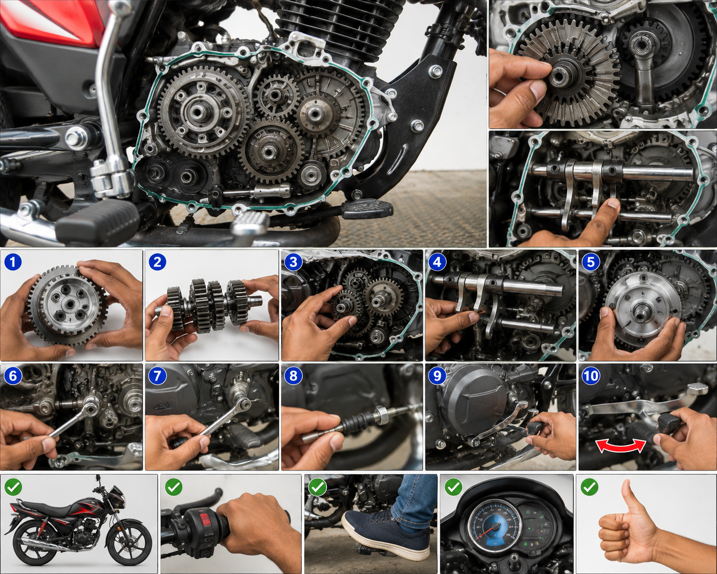
BS6 Bike Repair in 2026: Step-by-Step Guide for Beginners and Mechanics

BS6 Bike Repair in 2026: Step-by-Step Guide for Beginners and Mechanics


BS6 bikes are built to meet stricter emission rules, so they use fuel injection, sensors, and more electronic parts t‌han older models. That means repairs can take a different path, especially when a rough idle, warning light, or starting issue shows up.

The good news is that most common problems still follow a clear BS6 bike repair process, even if you’re new to the work. This guide helps DIY riders and mechanics cut out guesswork, save time, and stop small faults from turning into expensive damage. Start with the basics, then move step by step into the checks that matter most.

In this advanced technical manual, we will break down the diagnostic steps for Electronic Fuel Injection (EFI) fuel pumps, testing throttle position and O2 sensors, reading OBD error codes, and troubleshooting battery-draining faults to ensure your BS6 motorcycle delivers peak performance and compliance.


Know Your BS6 Bike Before You Touch a Single Bolt

A BS6 bike can look simple on the outside and still hide a lot under the tank and side covers. Before any repair starts, you need the exact model, engine setup, and fuel system. That information shapes every test, every part order, and every adjustment you make.

This matters because BS6 bikes are not all built the same. Two bikes from the same brand can use different injectors, sensors, ECU maps, or clutch setups. If you guess wrong, you waste time and may fit the wrong part.

Find the exact model, engine type, and fuel system

Next, look at the VIN or chassis number. You can usually find it on the steering head, frame tube, or registration papers. Match that number with the bike’s paperwork, because the same name on the tank can hide different versions underneath.

If the manual, VIN, and bike label do not match, trust the VIN and the registration details first.

Also check the sticker or label on the frame, swingarm, or under the seat. Many BS6 bikes carry emission or type labels that point to the engine family and fuel system. That small label can save you from ordering the wrong gasket, sensor, or injector.

Do not assume the bike has a carburetor style system just because an older version did. BS6 bikes are usually fuel injected, and that changes how they start, idle, and respond to throttle. A carburetor bike and a fuel-injected bike may share the same body shape, but they do not share the same repair logic.

Fuel injection details matter because the system depends on pressure, sensors, and ECU control. The fuel pump, injector, throttle body, and oxygen sensor all work together. If one part is off, the bike can run poorly even when the engine itself is fine.Understand the main BS6 parts that fail most often

Once you know the exact bike, focus on the parts that fail most often. These are the first places to check when a BS6 bike starts acting up.

A few common trouble spots are easy to remember:

  • Spark plug: A worn or fouled plug can cause misfire, hard starting, and poor pickup.
  • Battery: A weak battery affects starting and can confuse electronic systems.
  • Air filter: A clogged filter reduces airflow and hurts throttle response.
  • Fuel pump and injector: These control fuel delivery, so faults here often cause stalling or rough running.
  • Throttle body: Dirt buildup can upset idle speed and make the bike feel jerky.
  • O2 sensor: A bad sensor can send the wrong signal to the ECU and throw off fuel mix.
  • Clutch cable or hydraulic system: Problems here make shifting and takeoff feel heavy or uneven.
  • Brake pads and chain: These wear items affect safety and smooth riding.
  • ECU-related issues: Sensor faults, wiring damage, or bad connectors can trigger odd behavior across the bike.

Start with simple checks before replacing expensive parts. A dirty air filter can look like a fuel fault, and a weak battery can look like an ECU problem. That is why BS6 repair rewards a clear order of inspection.

Spot the warning signs before a small problem becomes a big repair

BS6 bikes usually give warning signs before a full breakdown. The trick is to catch them early and treat them as clues, not random noise.

Watch for these common symptoms:

  • Hard starting: The engine cranks longer than usual or refuses to fire up quickly.
  • Rough idle: The bike shakes or hunts at stoplights.
  • Poor mileage: Fuel use rises without a clear reason.
  • Engine stall: The bike cuts out at idle, low speed, or after warming up.
  • Check engine light: The ECU has stored a fault and wants attention.
  • Smoke: Excess smoke can point to fuel, oil, or combustion problems.
  • Vibration: New vibration can mean misfire, chain issues, or loose parts.
  • Weak brakes: Longer stopping distance or a spongy feel needs immediate attention.
  • Unusual noise: Knocking, clicking, squealing, or grinding should never be ignored.

Small symptoms often lead to bigger faults if you wait too long. A dirty injector, failing battery, or loose connector can grow into a harder-starting engine or a damaged catalyst. Early diagnosis costs less, takes less time, and protects the engine before the problem spreads.

Start with the bike’s identity, then move to the likely weak points. That order keeps your BS6 bike repair work clean, safe, and accurate.

Use a Safe Repair Routine That Works for Most BS6 Bikes

A good BS6 bike repair routine starts with control, not speed. When you work in the right order, you protect the bike, your tools, and your time.

Most faults on BS6 motorcycles can be handled with the same basic process. Start safe, diagnose in order, fix the real fault, then test the bike before you call the job done.

Start with safety, tools, and a clean work area

Before you touch a bolt, set up the space properly. Work on a cold engine, park the bike on stable ground, and disconnect the battery when the repair involves wiring, sensors, or the starter circuit.

Keep the basics close at hand:

  • Spanners and a socket set for fasteners and brackets
  • Screwdriver set for covers, clamps, and small fittings
  • A multimeter for battery, continuity, and sensor checks
  • A gauge for tire pressure or fluid checks, depending on the job
  • A torque wrench for correct final tightening
  • A scan tool, if your bike supports one, for fault codes and live data

Keep removed parts in trays, bags, or labeled containers. That habit saves you from loose bolts, mixed-up spacers, and missing clips later. Clean surroundings matter too, because dirt around injectors, connectors, and brake parts can create a second problem while you fix the first.

If the repair needs battery power, sensors, or fuel-line work, disconnect first and reconnect only after everything is back in place.

Diagnose the problem in the right order, not by guesswork

Start with the simplest checks and move outward. On most BS6 bikes, that means fuel, air, spark, battery, sensors, electrical connections, then mechanical parts.

A steady order like this keeps you from changing random parts. A new injector will not fix a blocked air filter, and a fresh spark plug will not cure a weak battery. Guesswork costs money, but it also hides the real fault and can create new ones.

A clear check sequence looks like this:

  1. Check fuel level, fuel quality, and fuel delivery.
  2. Inspect the air filter and intake path.
  3. Test the spark plug and ignition parts.
  4. Check battery voltage and charging health.
  5. Read sensors and fault codes if the bike has them.
  6. Inspect connectors, fuses, grounds, and wiring.
  7. Look at mechanical parts, such as clutch, compression, chain, and valve noise.

Start with the owner’s manual. It usually lists the model code, engine capacity, fuel system, and service intervals. If the bike came with a service book, check the first pages and stamped service records too. Those details often match the exact variant sold in your market.

Use the scan tool when available, but do not trust it alone. A fault code points you in the right direction, then physical checks confirm the cause. In other words, the code is a clue, not the whole case file.

Repair, test, and confirm the fix before riding

Once you find the fault, clean, repair, or replace the part with care. Tighten fasteners to the correct torque, refit hoses and clips properly, and reset fault codes only after the repair is complete.

Then test the bike in stages. Let it idle first, watch for smooth running, and listen for rough sounds or uneven revs. After that, take a short ride and check throttle response, clutch feel, braking, and gear changes.

Finish every repair with a full walk-around. Look for fuel, oil, or coolant leaks, check warning lights, and listen for rattles, tapping, or squealing. If something still feels off, stop and recheck it before the bike goes back on the road.

Handle the most common BS6 bike problems with confidence

Most BS6 bike faults fall into a few clear patterns. If you know the common weak points, you can move faster and avoid replacing parts that still work.

Start with the symptoms the rider can feel or hear. Then check the system behind them, one piece at a time. That approach works better than guessing, especially on bikes with fuel injection and sensors.

Fix starting trouble, weak battery issues, and charging problems

Starting trouble on a BS6 bike often points to the battery first. A weak battery can cause slow cranking, yes, but it can also trigger odd electronic faults, false warning lights, and unstable sensor readings. When voltage drops, the ECU, fuel pump, and starter relay may all act up at once.Check the battery health before anything else. Look for swollen casing, corrosion on the terminals, and loose clamps. A battery that looks fine can still fail under load, so test the voltage if the bike cranks slowly or clicks without starting.

A quick fault list helps narrow it down:

  • Loose terminals can interrupt power and make the bike seem dead.
  • Blown fuses can cut fuel pump, ignition, or ECU power.
  • Starter relay problems often show up as clicking with no crank.
  • Charging faults point to the alternator, stator, or regulator-rectifier.

If the bike starts with a jump but dies again later, the charging system needs attention. Check charging output with a multimeter, then inspect the alternator and regulator connections for heat damage, burns, or loose plugs. Bad grounding can mimic a failed part, so clean the terminals before you replace anything.

A battery that cannot hold charge can create more than starting trouble. On a BS6 bike, it can make the whole electrical system behave unpredictably.

Solve rough idle, jerking, and poor pickup

Rough idle, jerking, and weak pickup usually show up together. The bike may feel fine for a few minutes, then stumble at stoplights or surge when you open the throttle. Those are classic signs of airflow, fuel, or sensor trouble.Start with the throttle body. Dirt on the throttle plate can upset idle control and make the bike feel rough at low speed. Next, check the air filter. A blocked filter chokes airflow and makes the engine lazy under throttle.

Fuel quality matters too. Old or dirty fuel can cause hesitation, especially after long storage. Injector deposits can do the same, so listen for uneven running and watch for hard starts after refueling. Vacuum leaks around hoses or intake boots also create lean running and unstable idle

Sensor readings matter when the basics check out. If the throttle position, intake air, or oxygen sensor reads out of range, the ECU may send the wrong fuel mix. That often feels like surging, flat spots, or poor response when you roll the throttle open.

Repair brake, chain, clutch, and suspension wear before it gets worse

These parts are not comfort items, they are safety parts. A worn brake pad, stretched chain, or leaking fork can turn a normal ride into a risky one fast.Check the brake pads first. If the pad material looks thin or uneven, replace it. Also watch the brake fluid level and color. Low or dark fluid can point to wear, air, or old fluid that needs flushing.

For the chain, look at slack, dry links, and hooked sprocket teeth. Too much slack gives jerky power delivery, while tight spots can damage the gearbox and swingarm. If the sprocket teeth look sharp or curved, replace the set together. 

Clutch play matters too. Too much free play can make shifting rough, while too little can cause clutch slip. Check the lever feel and cable or hydraulic action before you adjust anything.Finally, inspect the suspension.read also car-maintenancecar-safety-tipsdashboard-warning-lights

 Conclusion 

Repairing and maintaining a BS6 motorcycle doesn’t have to be overwhelming. While fuel injection systems, sensors, and electronic components add complexity, following a structured diagnostic process makes troubleshooting straightforward and efficient. By starting with basic safety checks, inspecting high-wear components like spark plugs and batteries, and addressing warning symptoms early, you can keep any BS6 bike running smoothly and prevent costly engine repairs.

​Whether you are a beginner working in your home garage or a professional mechanic in a workshop, taking a methodical approach will always save you time and money. Stay patient, use the right tools, and double-check your work before hitting the road!

Fork oil on the tubes means a seal leak. A rear shock that bounces too long, sits low, or leaks oil needs repair or replacement. These faults affect braking, cornering, and tire grip, so they are not jobs to put off.

Hello friends! If you liked this technical guide, please be sure to share it with your friends. If you have any questions, feel free to leave a comment or send me an email—I’ll be happy to provide full guidance. Thank you!
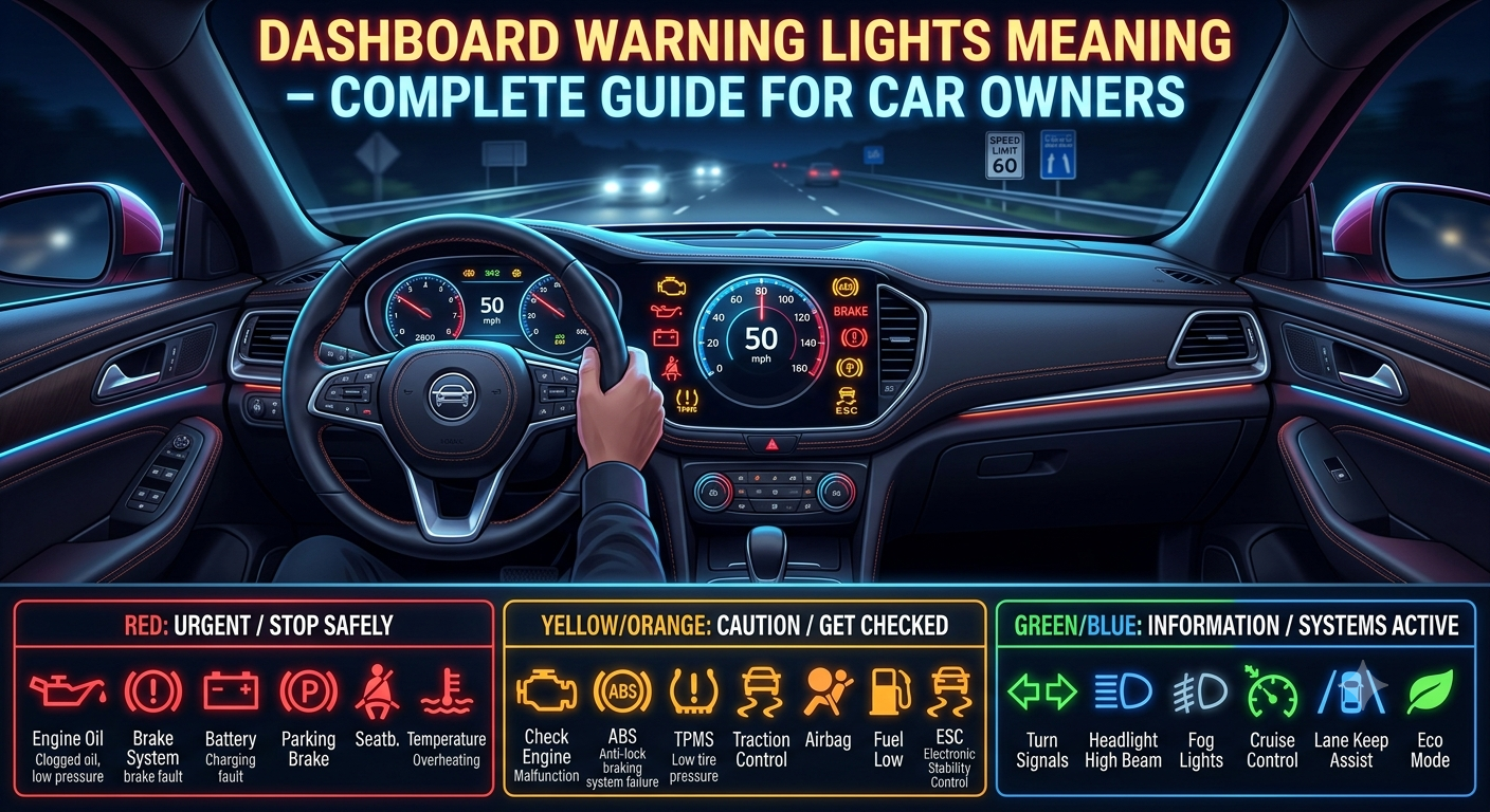

Dashboard Warning Lights Meaning – Complete Guide for Car Owners


Modern cars in 2026 are no longer simple mechanical machines. They are now smart electronic systems on wheels that constantly monitor every small activity inside the vehicle. From engine performance to braking system, from battery health to tire pressure — everything is tracked in real time using advanced sensors.

​One of the most important communication systems inside every modern car is the dashboard warning light system. These small symbols on your dashboard are not just decorative lights — they are your car’s way of talking to you.

​In this comprehensive technical guide, we will decode the exact meaning of these essential dashboard warning symbols, understand the difference between amber and red alert levels, and learn what immediate actions you must take to prevent costly mechanical failures and ensure on-road safety.

One of the most important communication systems inside every modern car is the dashboard warning light system. These small symbols on your dashboard are not just decorative lights — they are your car’s way of talking to you.

Whenever something goes wrong inside the vehicle, the system immediately displays a warning light. These warnings can range from simple notifications like headlights ON to serious alerts like engine failure or brake system problems.

The biggest issue is that most drivers do not understand the meaning of these lights. Many people ignore them or continue driving without realizing the seriousness of the problem. This negligence often leads to expensive repairs, breakdowns, or even dangerous accidents on the road.

In this complete 2026 guide, we will understand dashboard warning lights in simple language so that every car owner can easily identify problems early and take the right action.


What Are Dashboard Warning Lights?

Dashboard warning lights are small indicators displayed on your vehicle’s instrument cluster. These lights are connected to various sensors installed in different parts of your car.

Whenever a sensor detects an abnormal condition, it sends a signal to the car’s computer system (ECU), which then turns on the relevant warning light.

These lights help drivers understand:

  • What is happening inside the car
  • Whether the issue is minor or serious
  • When immediate action is needed

In simple words, dashboard lights act like a health report system for your vehicle.


Why Dashboard Warning Lights Are So Important

Ignoring dashboard warning lights is one of the biggest mistakes car owners make.

These lights are important because they:

  • Prevent major engine damage
  • Improve road safety
  • Reduce repair costs
  • Detect hidden problems early
  • Improve fuel efficiency
  • Protect engine, brakes, and transmission

A small warning today can prevent a major breakdown tomorrow.

For example, a simple oil warning light ignored for a few minutes can damage the entire engine. That is why understanding these lights is extremely important.


Types of Dashboard Warning Lights

Dashboard warning lights are divided into three major categories based on severity.


🟢 Green or Blue Indicator Lights (Normal Status)

These lights are not warnings. They simply show that a system is active.

Examples:

  • Headlights ON
  • Turn signals
  • Cruise control active
  • High beam indicator

👉 These lights do not indicate any problem. They only inform the driver.


🟡 Yellow or Orange Warning Lights (Caution)

Yellow lights indicate that something is not normal, but the vehicle can still be driven carefully.

Examples:

  • Check engine light
  • Tire pressure warning
  • ABS warning
  • Traction control warning

👉 These issues should be checked soon, but not always emergency.


🔴 Red Warning Lights (Danger)

Red lights indicate serious problems that require immediate attention.

Examples:

  • Engine overheating
  • Oil pressure warning
  • Brake system failure
  • Battery charging failure

👉 Red lights should NEVER be ignored. Stop the vehicle safely if possible.


Check Engine Light Explained

The check engine light is one of the most common and confusing warning lights.

It appears as an engine-shaped symbol on the dashboard.

Possible Causes:

  • Loose fuel cap
  • Faulty oxygen sensor
  • Engine misfire
  • Fuel injection issues
  • Emission system failure

Important Behavior:

  • Solid light → moderate issue
  • Blinking light → serious engine damage risk

👉 If the light is blinking, stop the vehicle immediately.


Oil Pressure Warning Light

This is one of the most dangerous warning lights in any car.

It looks like an oil can symbol.

Causes:

  • Low engine oil level
  • Oil pump failure
  • Oil leakage
  • Clogged oil filter

Why It Is Serious:

Engine oil lubricates all moving parts. Without proper oil pressure, engine components start rubbing against each other and can get damaged within minutes.

👉 If this light appears, stop the engine immediately.


Battery Warning Light

This light indicates a problem in the charging system.

Causes:

  • Weak or dead battery
  • Alternator failure
  • Loose terminals
  • Broken belt

What Happens:

If ignored, the car may suddenly lose power and stop running because the battery will not recharge properly.


Engine Temperature Warning Light

This light indicates engine overheating.

Causes:

  • Low coolant level
  • Radiator problem
  • Water pump failure
  • Cooling fan malfunction

Risks:

Overheating can damage:

  • Engine head
  • Gasket
  • Pistons
  • Entire engine block

👉 Always stop and allow the engine to cool down.


Brake Warning Light

The brake warning light is directly related to your safety.

Causes:

  • Low brake fluid
  • Worn brake pads
  • Parking brake engaged
  • Brake system fault

👉 If brakes fail, accident risk becomes extremely high.


ABS Warning Light

ABS (Anti-lock Braking System) helps prevent wheel locking during emergency braking.

If ABS Light Turns ON:

  • ABS system is not working
  • Normal braking may still function
  • Emergency braking safety is reduced

Tire Pressure Warning Light

This light indicates incorrect tire pressure.

Effects of Low Pressure:

  • Poor fuel economy
  • Uneven tire wear
  • Weak control
  • Risk of tire burst

👉 Always maintain correct PSI recommended by manufacturer.


Traction Control Warning Light

This system helps maintain grip on slippery roads.

Causes:

  • Slippery surface (rain, snow)
  • Sensor issue
  • System malfunction

Sometimes it blinks normally when system is actively working.


Airbag Warning Light

This indicates a problem in the safety airbag system.

Causes:

  • Faulty sensors
  • Wiring issues
  • Airbag module failure

👉 If this light stays ON, airbags may not deploy in an accident.


What Should Drivers Do When Warning Lights Appear?

Instead of panic, follow a logical approach:

  • Identify the symbol
  • Check owner’s manual
  • Inspect basic fluids
  • Avoid long driving if red light appears
  • Use diagnostic scanner if possible
  • Visit mechanic for inspection

👉 Quick action can save thousands in repair costs.


Modern Smart Car Diagnostic Systems (2026)

Modern vehicles are highly intelligent.

They can:

  • Monitor engine health in real time
  • Store error codes
  • Send alerts to mobile apps
  • Track fuel efficiency
  • Detect emissions problems

This makes cars safer and easier to maintain than ever before.


Common Mistakes Car Owners Make

Many drivers damage their cars due to ignorance.

Common Mistakes:

  • Ignoring warning lights
  • Resetting lights without fixing problem
  • Skipping oil changes
  • Driving overheating engine
  • Delaying service

👉 These mistakes lead to expensive repairs.


Real-Life Importance of Warning Lights

Imagine driving on a highway and suddenly the oil pressure light turns ON. If ignored, the engine may seize completely within minutes.

Or if brake warning light is ignored, braking performance may fail during emergency stopping.

That is why these lights are not optional  information — they are life-saving alerts.Read also clutch-shoe-replacementdiy-mechanicsscooter-maintenance


Final Thoughts

Dashboard warning lights are one of the most important safety features in modern vehicles. They are designed to protect your engine, brakes, transmission, and overall driving safety.

Understanding these lights helps you:

  • Avoid breakdowns
  • Save repair costs
  • Improve safety
  • Extend vehicle life
  • Drive with confidence

Some warnings are minor, but some are extremely serious and require immediate attention.

A smart driver never ignores dashboard signals. Instead, they understand them and act on time.

In simple words, dashboard warning lights are your car’s voice — and listening to it can save both your money and your life.

Hello friends! If you liked this technical guide, please be sure to share it with your friends. If you have any questions, feel free to leave a comment or send me an email—I’ll be happy to provide full guidance. Thank you!

How to Change Yamaha Scooter Clutch Shoes – Complete Step-by-Step Maintenance Guide (2026)


How to Change Yamaha Scooter Clutch Shoes – Complete Step-by-Step Maintenance Guide (2026)


The clutch shoe assembly is one of the most important parts of a scooter’s transmission system. Over time, clutch shoes wear out due to constant friction, which can lead to poor acceleration, vibration, unusual noises, and reduced riding performance.

In this comprehensive, step-by-step technical guide, you will learn the exact tools required, critical symptoms of worn clutch shoes, professional inspection procedures, removal methods, installation steps, and important maintenance tips to keep your Yamaha scooter running smoothly.

Whether you own a Yamaha Fascino, Ray ZR, RayZR 125, Aerox 155, Alpha or another Yamaha scooter model, this guide will provide you with the exact technical specifications and torque values needed to complete the clutch shoe replacement process safely and correctly.


What Are Clutch Shoes?

Clutch shoes are part of the scooter’s centrifugal clutch system.

When engine RPM increases, the clutch shoes expand outward and make contact with the clutch bell. This transfers engine power to the rear wheel and allows the scooter to move forward.

As the friction material wears down, clutch performance gradually decreases.


Signs of Worn Clutch Shoes

If your Yamaha scooter shows any of the following symptoms, the clutch shoes may need replacement:

Common Symptoms

  • Poor acceleration
  • Jerking during take-off
  • Vibrations while starting
  • Burning smell from CVT housing
  • Reduced pickup
  • Excessive clutch noise
  • Scooter struggles to move from a stop
  • Uneven engagement of power

Ignoring these symptoms may cause additional wear to the clutch bell and CVT components.


Tools Required

Prepare the following tools before starting:

Essential Tools

  • Socket set
  • Ratchet handle
  • Impact wrench (recommended)
  • Torque wrench
  • Screwdrivers
  • Pliers
  • Cleaning brush
  • Air blower

Replacement Parts

  • New Yamaha clutch shoe assembly
  • New clutch springs (if required)
  • CVT cover gasket (if applicable)
  • Transmission cleaner

Using genuine Yamaha parts is highly recommended for reliability and durability.


Safety Precautions

Before beginning the repair:

  • Park the scooter on a flat surface.
  • Use the center stand.
  • Turn off the ignition switch.
  • Remove the key.
  • Allow the engine to cool.
  • Wear safety gloves and eye protection.

A clean work area helps prevent contamination inside the CVT system.


Step 1: Remove the CVT Cover

The clutch assembly is located inside the CVT housing.

Procedure

  1. Remove all CVT cover bolts.
  2. Keep the bolts arranged properly.
  3. Carefully remove the transmission cover.
  4. Inspect the inside for dust accumulation.

You will now see the variator, drive belt, clutch assembly, and clutch bell.


Step 2: Inspect the CVT Components

Before disassembly, inspect:

Check For

  • Cracked drive belt
  • Worn pulley faces
  • Loose fasteners
  • Excessive clutch dust
  • Damaged clutch bell

Cleaning and inspection at this stage can prevent future problems.


Step 3: Remove the Clutch Bell

The clutch bell covers the clutch shoes.

Procedure

  1. Hold the clutch assembly securely.
  2. Remove the clutch bell nut.
  3. Slide off the clutch bell carefully.

Inspect the inner surface of the clutch bell.

Look For

  • Blue heat spots
  • Cracks
  • Deep grooves
  • Excessive wear

Replace the clutch bell if significant damage is found.


Step 4: Remove the Clutch Assembly

After removing the clutch bell:

  1. Remove the clutch assembly from the transmission shaft.
  2. Place it on a clean workbench.
  3. Inspect the entire assembly before dismantling.

This allows easier access to the clutch shoes.


Step 5: Inspect the Existing Clutch Shoes

Examine the clutch shoes carefully.

Check For

  • Thin friction material
  • Cracks
  • Oil contamination
  • Uneven wear
  • Broken springs

Worn friction material is the most common reason for clutch replacement.


Step 6: Compress the Clutch Assembly Safely

The clutch assembly contains a strong spring.

Important Safety Note

Always use a clutch spring compressor tool whenever possible.

This prevents accidental injury and protects components from damage.


Step 7: Remove the Clutch Shoes

Procedure

  1. Compress the assembly safely.
  2. Remove the retaining components.
  3. Release spring tension gradually.
  4. Remove the old clutch shoes.
  5. Remove old springs if necessary.

Take note of the original installation position.


Step 8: Clean All Components

Before installing new parts:

Clean

  • Clutch housing
  • Clutch bell
  • Spring seats
  • Shaft splines
  • Pulley area

Use approved transmission cleaner and compressed air.

Do not leave dust or grease on friction surfaces.


Step 9: Install New Clutch Shoes

Now install the new Yamaha clutch shoes.

Procedure

  1. Position each clutch shoe correctly.
  2. Install the retaining springs.
  3. Ensure proper alignment.
  4. Verify smooth movement of each shoe.

All shoes should move freely without binding.


Step 10: Reassemble the Clutch Unit

After installation:

  1. Compress the assembly carefully.
  2. Reinstall retaining hardware.
  3. Ensure proper seating of components.
  4. Release compression slowly.

Double-check that all parts are correctly positioned.


Step 11: Reinstall the Clutch Assembly

Procedure

  1. Slide the clutch assembly onto the shaft.
  2. Align splines correctly.
  3. Ensure proper seating.

Improper installation may cause vibration and transmission damage.


Step 12: Install the Clutch Bell

Procedure

  1. Clean the inside surface of the clutch bell.
  2. Slide it onto the clutch assembly.
  3. Install the retaining nut.
  4. Tighten according to Yamaha specifications.

Using a torque wrench is recommended.


Step 13: Inspect the Drive Belt

Since the CVT cover is already removed, inspect the drive belt.

Replace If

  • Cracked
  • Frayed
  • Excessively worn
  • Oil contaminated

Replacing worn CVT components together can save future labor costs.


Step 14: Reinstall the CVT Cover

Procedure

  1. Position the cover carefully.
  2. Install bolts by hand first.
  3. Tighten evenly in sequence.
  4. Ensure proper sealing.

Avoid overtightening aluminum threads.


Step 15: Perform a Functional Test

Before riding:

Check

  • Smooth clutch engagement
  • No unusual noises
  • Proper acceleration
  • Stable idle operation

Start the engine and allow it to warm up.


Step 16: Test Ride the Scooter

Conduct a short road test.

Observe

  • Take-off performance
  • Acceleration response
  • Vibrations
  • Noise levels

A properly installed clutch shoe set should provide smooth and consistent power delivery.


Common Mistakes to Avoid

Many clutch problems occur because of installation errors.

Avoid These Mistakes

  • Reusing damaged springs
  • Installing contaminated clutch shoes
  • Ignoring clutch bell wear
  • Overtightening nuts
  • Using low-quality aftermarket parts
  • Failing to clean CVT dust
  • Improper clutch assembly alignment

Correct installation greatly improves clutch life.


Maintenance Tips

To extend clutch shoe life:

  • Avoid aggressive launches.
  • Clean the CVT system periodically.
  • Inspect the drive belt regularly.
  • Replace worn transmission parts promptly.
  • Keep oil away from clutch surfaces.
  • Follow Yamaha maintenance schedules.

Regular maintenance ensures smooth performance and better fuel efficiency.  Read also toyota-fortuner-ac-cooling-issue


Conclusion

Replacing Yamaha scooter clutch shoes is an important maintenance procedure that restores smooth acceleration, improves power transfer, and eliminates clutch-related vibrations. By following the correct step-by-step method, using quality replacement parts, and inspecting all CVT components during service, you can achieve reliable performance and extend the life of your scooter’s transmission system. Proper maintenance not only improves riding comfort but also helps prevent costly repairs in the future.

Hello friends! If you liked this technical guide, please be sure to share it with your friends. If you have any questions, feel free to leave a comment or send me an email—I’ll be happy to provide full guidance. Thank you!

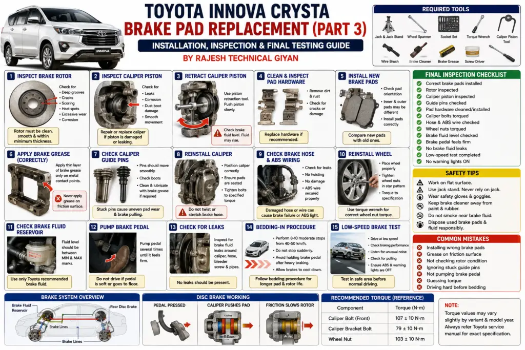
Toyota Innova Crysta Brake Pad Replacement: Step-by-Step Guide


  • “With over 10 years of hands-on automotive repair experience at Rajesh Technical Giyan, this guide breaks down the step-by-step procedure…”

In Part 1 and Part 2 of our Toyota Innova Crysta brake-pad replacement series, we discussed the importance of brake-pad maintenance, the required tools, wheel removal, brake-caliper inspection, and the basic procedure for removing the old brake pads.

In this Part 3, we will continue from the installation stage and focus on the most important final procedures.

After removing the old brake pads, simply installing new pads is not enough. A professional brake repair also requires inspection of the brake rotor, caliper, pad clips, guide pins, brake-fluid level, piston movement, and correct pad seating.

A small installation mistake can cause:

  • Uneven braking
  • Brake noise
  • Vehicle pulling to one side
  • Brake-pad overheating
  • Premature pad wear
  • Brake-fluid problems
  • Reduced braking performance

Therefore, the final inspection and testing stage is just as important as removing the old brake pads.

Important: Toyota Innova Crysta variants can have different brake configurations depending on model year, engine, trim level, and market. Always use the correct brake pads and manufacturer specifications for your exact vehicle.


Step 1: Inspect the Brake Rotor Before Installing New Pads

Before installing the new brake pads, carefully inspect the brake rotor or disc.

The new brake pads must make proper contact with a suitable rotor surface.

Check for Rotor Damage

Inspect the disc for:

  • Deep grooves
  • Cracks
  • Excessive scoring
  • Blue or dark heat spots
  • Uneven wear
  • Corrosion
  • Excessive lip formation
  • Abnormal surface damage

Light surface marks can sometimes be normal, but deep grooves or severe heat damage require further inspection.

Why Rotor Condition Matters

Installing new brake pads against a badly damaged rotor can result in:

  • Uneven pad contact
  • Brake vibration
  • Noise
  • Reduced braking efficiency
  • Premature pad wear

If the rotor is below the manufacturer’s minimum thickness or has serious damage, it should be replaced or serviced according to the manufacturer’s procedure.

Never machine or reuse a rotor without checking its specification.


Step 2: Inspect the Brake-Caliper Piston

The brake-caliper piston pushes the brake pad against the rotor when the brake pedal is pressed.

Before fitting the new pads, inspect the piston carefully.

Check for:

  • Brake-fluid leakage
  • Corrosion
  • Damaged piston surface
  • Torn dust boot
  • Dirt around the piston

A leaking or damaged caliper should be repaired before completing the brake-pad replacement.

Do Not Force a Damaged Piston

If the piston does not retract smoothly, do not use excessive force.

A sticking piston can indicate a caliper problem that needs proper diagnosis.


Step 3: Retract the Brake-Caliper Piston Correctly

New brake pads are normally thicker than worn pads.

Therefore, the caliper piston may need to be pushed back to create enough space for the new pads.

Use an appropriate piston-retraction tool.

Before retracting the piston, consider the brake-fluid level in the reservoir.

As the piston moves back, brake fluid may rise in the reservoir.

If the reservoir becomes too full, fluid can overflow.

Brake fluid can damage painted surfaces, so clean any spill immediately using an appropriate method.

Never use excessive force or an unsuitable tool that can damage the piston, dust boot, or caliper.


Step 4: Inspect and Clean the Brake-Pad Hardware

Brake-pad clips, shims, and retaining hardware are important for proper brake-pad movement.

Remove dirt, rust, and brake dust from the applicable contact areas.

Inspect the hardware for:

  • Rust
  • Deformation
  • Cracks
  • Weak retaining tension
  • Excessive wear

If the manufacturer recommends replacing the hardware with the brake pads, install new hardware.

Do not bend or modify brake-pad clips to make them fit.


Step 5: Install the New Toyota Innova Crysta Brake Pads

Before installation, compare the new pads with the old ones.

Check:

  • Shape
  • Thickness
  • Mounting points
  • Wear-indicator position
  • Shim arrangement
  • Left/right or inner/outer configuration where applicable

The new pads should match the correct application for your vehicle.

Check Pad Orientation

Some brake-pad sets use different inner and outer pads.

Never assume that all four pads are identical.

Follow the pad markings and vehicle-specific service information.

Install each pad in its correct position.


Step 6: Apply Brake-Assembly Lubricant Correctly

Some brake-pad contact points may require a suitable brake lubricant.

However, lubricant should never be applied to the friction surface.

Never put grease or lubricant on:

  • Brake-pad friction material
  • Rotor braking surface
  • Any surface intended to generate friction

If lubrication is specified, apply only a small amount to the appropriate metal contact points using a brake-compatible product.

Too much lubricant can attract dust and contaminate the brake system.


Step 7: Inspect the Caliper Guide Pins

The caliper guide pins allow the caliper to move correctly.

A seized or contaminated guide pin can cause uneven brake-pad wear.

Check whether the guide pins:

  • Move smoothly
  • Are clean
  • Have proper lubrication where specified
  • Have intact rubber boots
  • Show no excessive corrosion

If a guide pin is stuck, do not simply force it back into place.

Remove, inspect, clean, and lubricate it according to the manufacturer’s procedure.

If damaged, replace the necessary components.


Step 8: Reinstall the Brake Caliper

After installing the new brake pads, carefully position the brake caliper back into place.

Make sure:

  • Pads remain correctly seated.
  • Hardware is correctly positioned.
  • Guide pins are correctly aligned.
  • Brake hose is not twisted.
  • No wiring or sensor cable is trapped.
  • Caliper mounting surfaces are clean.

Tighten the caliper fasteners using the correct manufacturer-specified torque.

Do not guess brake-caliper bolt torque. Always use the Toyota service specification for the exact Innova Crysta variant.


Step 9: Check the Brake Hose and ABS Wiring

Before reinstalling the wheel, inspect the brake hose and ABS wiring.

Look for:

  • Cracks
  • Cuts
  • Leaks
  • Twisting
  • Chafing
  • Loose clips
  • Damaged insulation

The ABS sensor wiring should be routed correctly and secured away from moving or hot components.

A damaged ABS wire can trigger an ABS warning and affect the vehicle’s electronic braking systems.


Step 10: Reinstall the Wheel

Once the brake assembly has been inspected, reinstall the wheel.

Before tightening the wheel nuts, make sure the wheel is sitting correctly against the hub.

Tighten the wheel nuts gradually in a cross pattern.

Use a calibrated torque wrench and the manufacturer’s specified wheel-nut torque.

Do not rely on an impact wrench alone for final tightening.


Step 11: Check the Brake-Fluid Reservoir

After retracting the caliper piston, check the brake-fluid reservoir.

The fluid level should be within the manufacturer’s specified range.

Do not simply add fluid without checking why the level is low.

A low brake-fluid level may indicate:

  • Pad wear
  • Leakage
  • Hydraulic-system problems

If the brake fluid is contaminated or due for replacement, follow the manufacturer’s service procedure.


Step 12: Pump the Brake Pedal Before Driving

This is one of the most important steps after brake-pad replacement.

Before moving the vehicle, press the brake pedal several times.

Initially, the pedal may feel softer or travel farther because the caliper piston was retracted.

Continue pumping the brake pedal until the pedal becomes firm.

Never Drive With a Soft Brake Pedal

If the pedal remains excessively soft or sinks toward the floor, stop the repair process.

Inspect for:

  • Brake-fluid leakage
  • Incorrect pad installation
  • Caliper problems
  • Hydraulic-system problems
  • Air in the brake system

Do not drive the vehicle until the braking system has been properly diagnosed.


Step 13: Check for Brake-Fluid Leaks

Inspect the complete brake assembly.

Look around:

  • Caliper
  • Brake hose
  • Brake-pipe connections
  • Master-cylinder area
  • Reservoir
  • Bleeder screw

There should be no visible brake-fluid leakage.

If any leak is detected, do not operate the vehicle.


Step 14: Brake Pad Bedding-In Procedure

New brake pads require proper bedding-in so that the friction surfaces can establish suitable contact with the brake rotor.

The exact bedding procedure depends on the brake-pad manufacturer.

In general:

  1. Drive in a safe area.
  2. Perform several moderate braking applications.
  3. Avoid aggressive emergency-style braking during the initial bedding period unless required for safety.
  4. Allow the brakes to cool between repeated applications when appropriate.
  5. Avoid keeping the brake pedal continuously pressed after heavy braking when the brakes are extremely hot.

Do not perform bedding-in procedures on public roads where it would be unsafe.

Always follow the brake-pad manufacturer’s recommended bedding procedure if one is provided.


Step 15: Perform a Low-Speed Brake Test

After completing the installation, test the vehicle at low speed in a safe location.

Check:

  • Brake-pedal feel
  • Vehicle stopping response
  • Unusual noise
  • Steering pull
  • Brake vibration
  • ABS warning light
  • Brake warning light

The vehicle should stop smoothly and predictably.

If it pulls strongly to one side, stop and investigate.


Step 16: Listen for Abnormal Brake Noise

Some light noise can occur during the initial bedding process, but persistent or severe noise should not be ignored.

Possible causes include:

  • Incorrect pad installation
  • Loose hardware
  • Dry or seized guide pins
  • Rotor surface problems
  • Contaminated brake pads
  • Incorrect brake-pad type

Never assume that loud grinding or severe vibration is normal after installing new brake pads.


Common Mistakes During Brake-Pad Replacement

Mistake 1: Installing the Wrong Brake Pads

Always verify the correct part application before installation.

Mistake 2: Contaminating the Friction Surface

Never touch the friction surface with greasy hands or apply lubricant to it.

Mistake 3: Ignoring the Rotor

New brake pads cannot compensate for a severely damaged or worn rotor.

Mistake 4: Failing to Check Guide Pins

A seized guide pin can cause uneven pad wear and overheating.

Mistake 5: Not Pumping the Brake Pedal

Always restore proper pedal feel before moving the vehicle.

Mistake 6: Guessing Torque Specifications

Use the correct Toyota service specifications for caliper and wheel fasteners.

Mistake 7: Driving Aggressively Immediately After Installation

Allow the new pads to bed in according to the manufacturer’s instructions.


How to Know Your New Brake Pads Are Working Properly

After installation and bedding, the braking system should provide:

  • Consistent pedal feel
  • Smooth braking
  • No severe vibration
  • No abnormal grinding
  • No strong pulling
  • No brake-fluid leakage
  • No unexpected warning lights

A small amount of initial noise can sometimes occur, but persistent symptoms require inspection.


Toyota Innova Crysta Brake Pad Replacement Checklist

Before handing the vehicle back to the customer, I recommend checking the following:

  • [ ] Correct brake pads installed
  • [ ] Rotor inspected
  • [ ] Brake-pad hardware checked
  • [ ] Caliper piston inspected
  • [ ] Guide pins checked
  • [ ] Caliper fasteners tightened correctly
  • [ ] Brake hose inspected
  • [ ] ABS wiring checked
  • [ ] Wheel installed correctly
  • [ ] Wheel nuts torqued correctly
  • [ ] Brake-fluid level checked
  • [ ] Brake pedal pumped
  • [ ] No visible brake-fluid leakage
  • [ ] Low-speed brake test completed
  • [ ] Warning lights checked
  • [ ] Brake pads bedded in correctly

Frequently Asked Questions

How long does it take to replace Toyota Innova Crysta brake pads?

The actual time depends on the vehicle condition, mechanic experience, brake configuration, and whether additional problems such as seized guide pins or worn rotors are found.

Do I need to replace the brake rotor every time I replace the brake pads?

Not necessarily.

The rotor should be inspected and measured against the manufacturer’s specifications. If it is within specification and in good condition, replacement may not be required.

Why does my brake pedal feel soft after replacing brake pads?

The caliper piston may still be retracted, or there may be another hydraulic or installation issue.

Pump the pedal before moving the vehicle. If it does not become firm, stop and inspect the braking system.

Do new brake pads need bedding?

Yes, new pads generally benefit from an appropriate bedding procedure. Follow the brake-pad manufacturer’s instructions whenever available.

Can I apply grease to the brake pad?

Never apply grease to the friction material or rotor.

Only use a suitable brake lubricant on specified metal contact points when required.

Why does my Innova Crysta pull to one side after brake-pad replacement?

Possible causes include uneven pad contact, a sticking caliper or guide pin, contamination, rotor problems, tyre issues, or another suspension/braking fault.

The vehicle should be inspected rather than driven normally until the cause is identified.


Professional Mechanic’s Final Advice

Brake-pad replacement may look like a simple maintenance job, but brakes are one of the most important safety systems on any vehicle.

A professional repair should not stop after fitting the new pads.

The mechanic should inspect the rotor, caliper, guide pins, hardware, brake hose, ABS wiring, brake-fluid level, and pedal operation.

The final road test should also be performed carefully in a safe environment.

At Rajesh Technical Giyan, my approach is simple:

Inspect → Replace → Torque → Check → Test

Never rush a brake repair.

Correct installation, proper inspection, and careful testing can help ensure reliable braking performance and safer drivingktm-bike-cylinder-head-fitting-procedure-a-complete-mechanics-step-by-step-guide


Conclusion

Replacing the brake pads on a Toyota Innova Crysta is an important maintenance procedure, but proper installation is only one part of the job.

After fitting the new pads, the rotor, caliper piston, guide pins, brake hardware, brake hose, ABS wiring, brake-fluid level, and wheel installation should all be inspected carefully.

The brake pedal must be restored to a firm and consistent condition before the vehicle is moved.

Finally, the new pads should be bedded in correctly and the vehicle should undergo a controlled low-speed brake test.

Remember:

Never compromise on brake safety.

If you are unsure about any part of the brake system, consult a qualified automotive technician and use the correct Toyota service information for your specific Innova Crysta.

Stay safe, maintain your vehicle with care, and keep learning automotive repair skills.

— Rajesh
Rajesh Technical Giyan

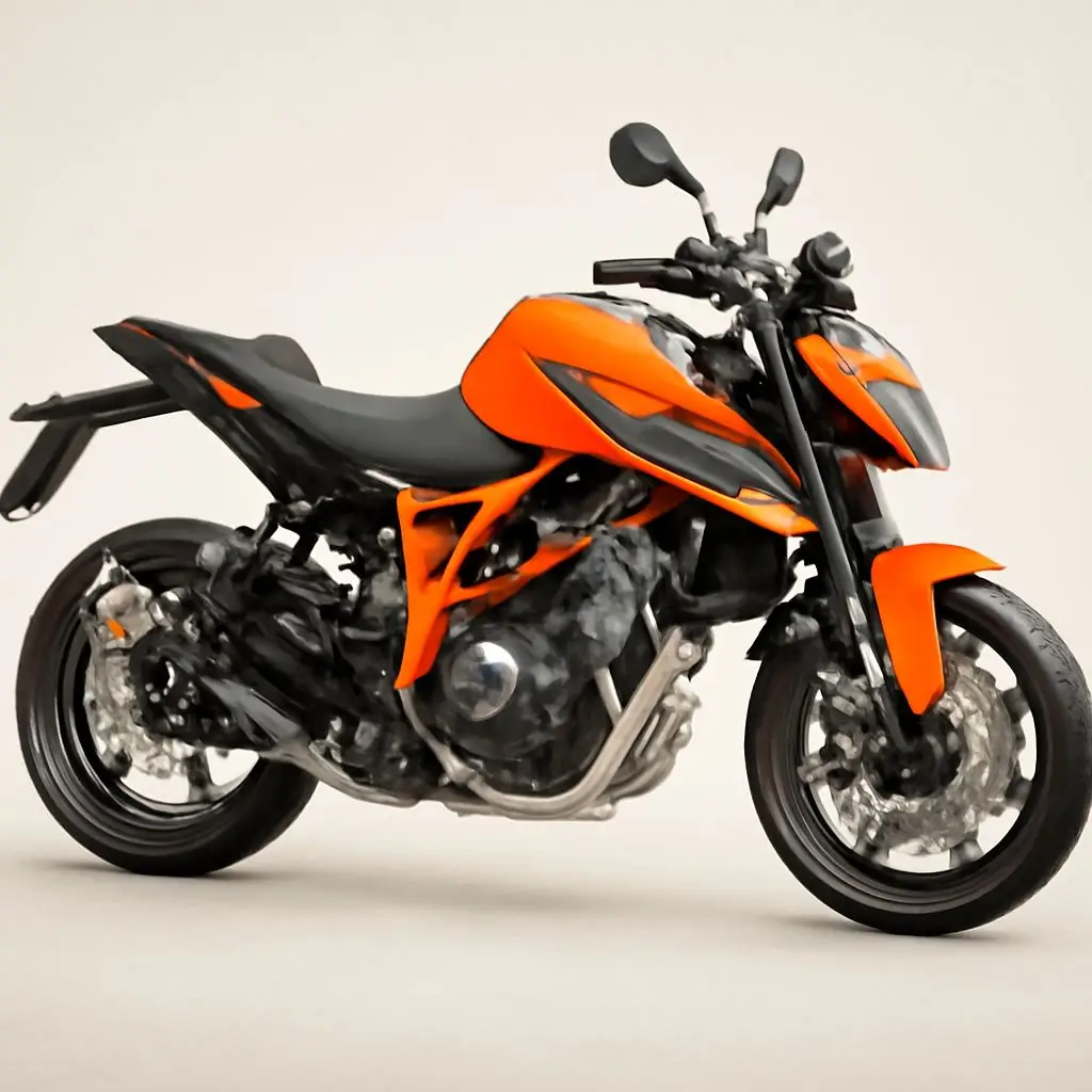
KTM Cylinder Head Fitting: Complete Step-by-Step Guide

  • “Fitting or rebuilding the cylinder head on a high-revving, liquid-cooled KTM engine requires precision, cleanliness, and strict attention to the manufacturer’s specifications. A small mistake in cam timing, bolt tightening, gasket installation, or valve clearance can cause serious engine problems.”

In this guide, I will explain a professional KTM motorcycle cylinder head fitting procedure, including surface preparation, head-gasket installation, cylinder-head tightening, TDC positioning, camshaft timing, valve-clearance checking, tensioner installation, and final inspection.

Important: KTM has several engine generations and models, including 125cc, 200cc, 250cc and 390cc variants. Torque values, timing marks, valve clearances, tightening sequences, and procedures can differ between models and model years. Always verify the exact specifications in the workshop manual for your motorcycle before assembly.


Required Tools, Equipment, and Supplies

Before starting the cylinder-head installation, prepare all required tools and replacement parts.

  • Precision torque wrench
  • 1/4-inch and 3/8-inch drive sockets
  • Metric socket set
  • Allen keys
  • T25 and T30 Torx tools where applicable
  • Feeler gauge set
  • Digital vernier caliper
  • Micrometer for measuring valve shims
  • Engine assembly lubricant
  • Clean recommended motorcycle engine oil
  • Genuine or manufacturer-approved cylinder-head gasket
  • New required sealing gaskets and O-rings
  • Plastic or suitable gasket scraper
  • Brake cleaner or approved cleaning solvent
  • Lint-free workshop towels
  • Compressed air
  • Nitrile gloves
  • Suitable flywheel/TDC locking tool where specified
  • Workshop manual for the exact KTM model

Good preparation is important because cylinder-head assembly should not be interrupted repeatedly to search for tools or replacement parts.


Step 1: Surface Preparation and Cleaning

The cylinder-head gasket can only create a reliable seal when the mating surfaces are clean, flat, and free from damage.

Clean the Cylinder Surface

Carefully clean the top mating surface of the cylinder barrel.

Remove:

  • Old gasket material
  • Carbon deposits
  • Oil residue
  • Coolant residue
  • Dirt and dust

Use an appropriate plastic or non-damaging scraper. Avoid aggressively scraping aluminum surfaces with hard steel tools because scratches or gouges can create sealing problems.

Clean the Cylinder-Head Deck

Clean the underside of the cylinder head thoroughly.

Inspect the surface for:

  • Scratches
  • Corrosion
  • Burn marks
  • Warping
  • Previous gasket failure
  • Coolant or oil contamination

If the surface appears warped or damaged, it should be checked using appropriate measuring equipment. Do not assume a damaged cylinder head will seal simply because a new gasket is installed.

Clean the Bolt Holes

The cylinder-head bolt or stud holes should be clean and free from oil, coolant, dirt, and debris.

Contamination inside threaded holes can affect torque readings and may prevent correct clamping force.

Use compressed air carefully and follow the manufacturer’s procedure for cleaning threaded holes.

Check the Dowel Pins

Install the original alignment dowel pins in their correct positions.

These dowels help locate the cylinder head and gasket accurately.

Never omit a required dowel pin.


Step 2: Installing the New Cylinder-Head Gasket

Always use a new cylinder-head gasket of the correct specification.

A head gasket should not normally be reused after removal because its sealing characteristics may be compromised.

Gasket Installation Procedure

  1. Confirm that the cylinder and cylinder-head surfaces are clean and dry.
  2. Place the new gasket over the alignment dowel pins.
  3. Check the gasket orientation carefully.
  4. Confirm that all oil passages, coolant passages, and cylinder openings line up correctly.
  5. Make sure the gasket is sitting completely flat.

Do not apply RTV silicone, grease, or liquid gasket to an MLS gasket unless the KTM workshop manual specifically requires it.

Using an incorrect sealant can interfere with the gasket’s designed sealing characteristics.


Step 3: Mounting the Cylinder Head

Carefully lower the cylinder head onto the cylinder barrel.

Do not force the head into position.

Make sure:

  • The dowel pins are correctly located.
  • The gasket remains properly positioned.
  • The timing chain is accessible through the timing-chain passage.
  • No wires, hoses, or other components are trapped underneath the cylinder head.

Pull the timing chain upward and secure it temporarily with suitable mechanic’s wire or a clean retaining method so that it does not fall into the crankcase.


Step 4: Cylinder-Head Bolt Installation and Tightening

Correct tightening is one of the most important parts of cylinder-head assembly.

The bolts, nuts, washers, and threads should be clean and inspected before installation.

Do not automatically lubricate fasteners unless the KTM workshop manual specifies the required lubrication procedure. Torque specifications are based on a particular fastener condition, and changing the lubrication condition can change the actual clamping force.

Use a Cross or Manufacturer-Specified Sequence

Cylinder-head fasteners should generally be tightened progressively and in the sequence specified by KTM.

A typical workshop process may involve several stages rather than applying the final torque immediately.

Important Torque Warning

Do not use a generic torque value for every KTM engine.

For example, a KTM 125, 200, 250, and 390 engine can have different:

  • Cylinder-head fasteners
  • Torque values
  • Tightening sequences
  • Fastener designs
  • Torque-angle requirements
  • Model-year specifications

Therefore, the exact final torque must be taken from the workshop manual for the specific engine being repaired.

Never guess cylinder-head torque specifications.

Incorrect torque can cause gasket failure, stripped threads, distorted components, coolant leakage, or serious engine damage.


Step 5: Setting the Engine to Top Dead Center (TDC)

Before installing and timing the camshafts, position the crankshaft correctly at Top Dead Center (TDC) according to the KTM service procedure.

TDC provides the correct crankshaft reference point for camshaft timing.

Basic Procedure

  1. Rotate the crankshaft using the correct tool.
  2. Locate the manufacturer’s TDC timing reference.
  3. Align the crankshaft timing mark according to the workshop manual.
  4. Use the approved crankshaft locking procedure if required.
  5. Confirm that the piston position corresponds to the required timing position.

Do not rely only on approximate visual positioning.

Important Safety Warning

If a crankshaft locking pin is installed, never force the engine to rotate against the locking pin.

Before manually rotating the crankshaft, remove the locking tool unless the service procedure specifically states otherwise.

Forcing the crankshaft against a locking tool can damage the crankshaft, crankcase, flywheel, or locking tool.


Step 6: Installing the Camshafts and Setting DOHC Timing

Many KTM engines use DOHC architecture with separate intake and exhaust camshafts.

Correct camshaft timing is critical.

Even a small timing error can cause poor engine performance, hard starting, misfiring, overheating, or piston-to-valve contact depending on the engine design.

Lubricate the Camshaft Components

Apply the manufacturer’s recommended assembly lubricant or clean engine oil to the camshaft journals and other specified lubrication points.

Do not run a freshly assembled cylinder head with dry camshaft journals.

Install the Exhaust Camshaft

Position the exhaust camshaft according to the correct timing marks.

Place the timing chain over the sprocket while maintaining the correct chain position.

Install the Intake Camshaft

Install the intake camshaft in its correct position.

Ensure the timing chain is correctly seated on both sprockets.

The timing marks must match the manufacturer’s specified reference position.

Check Timing-Chain Slack

Keep the appropriate side of the timing chain taut while positioning the camshafts.

Incorrect chain slack during timing setup can cause the timing marks to appear correct initially but become incorrect when the tensioner is installed.


Step 7: Installing Camshaft Bridge Caps

Once the camshafts are correctly positioned, install the camshaft retaining caps or bridge components.

Make sure:

  • Each cap is installed in its original position.
  • The correct orientation is maintained.
  • Dowel pins are properly seated.
  • Lubrication passages are not blocked.
  • The camshafts remain correctly positioned.

Tighten the camshaft bridge fasteners gradually and in the manufacturer-specified sequence.

Because the cylinder head is aluminum, overtightening small camshaft fasteners can damage the threads or distort the camshaft bearing area.

Use only the exact torque specification given in the KTM workshop manual for your particular engine.

Do not apply thread locker unless the service manual specifically requires it.


Step 8: Installing the Cam Chain Tensioner

The cam-chain tensioner controls timing-chain slack.

Before installation:

  1. Inspect the tensioner.
  2. Confirm that its locking/reset mechanism works correctly.
  3. Install the required new gasket or sealing component.
  4. Position the tensioner correctly.
  5. Tighten the mounting fasteners to the manufacturer’s specified torque.
  6. Release or activate the tensioner according to the service procedure.

Do not manually force the tensioner beyond its designed operating range.

An incorrectly installed or improperly reset tensioner can cause timing-chain noise, timing errors, or chain jumping.


Step 9: Rechecking Camshaft Timing

This is one of the most important inspection stages.

After installing the camshafts and tensioner, carefully rotate the engine by hand according to the manufacturer’s procedure.

Generally, the engine should be rotated through complete crankshaft revolutions and returned to the correct timing position.

Then check:

  • Crankshaft timing reference
  • Intake camshaft timing mark
  • Exhaust camshaft timing mark
  • Timing-chain position
  • Tensioner operation

The timing marks should return to the correct reference positions.

If the marks do not align, do not start the engine.

Remove the required components and correct the timing before proceeding.


Step 10: Checking Valve Clearance

Valve clearance must be checked with the engine in the correct position and under the conditions specified by KTM.

Use a clean feeler gauge to measure the clearance between the specified components.

Valve clearance specifications vary between KTM models and engine generations.

Therefore, do not use a generic clearance range as the final specification.

Always compare your measurement with the exact factory specification for your motorcycle.

If Valve Clearance Is Incorrect

If the clearance is outside specification:

  1. Record the measured clearance.
  2. Determine the required adjustment.
  3. Remove the required camshaft components following the service manual.
  4. Measure the existing shim.
  5. Calculate the required shim thickness.
  6. Install the correct shim.
  7. Reassemble the camshaft components.
  8. Recheck valve clearance.

A digital micrometer can be used to measure shim thickness accurately.


Step 11: Valve Cover Installation

Once valve clearance and camshaft timing have been confirmed, install the valve cover.

Inspect the valve-cover gasket carefully.

If the manufacturer specifies a new gasket, install a new one.

Place the gasket correctly into its groove and make sure it is not twisted or pinched.

If the service manual specifies sealant at particular joints or corners, apply only the recommended amount and type.

Do not apply excessive RTV sealant.

Tighten the valve-cover fasteners evenly using the manufacturer’s specified torque.


Step 12: Reconnecting Engine Components

Reconnect all components removed during the cylinder-head repair.

Depending on the KTM model, this may include:

  • Spark-plug cap
  • Ignition components
  • Coolant hoses
  • Intake manifold
  • Throttle-body connections
  • Fuel injector connector
  • Electrical connectors
  • Exhaust header
  • Sensors
  • Breather hoses
  • Airbox components

Check every connector and hose before starting the engine.

A loose vacuum hose, electrical connector, coolant hose, or fuel connection can cause serious running problems or leaks.


Step 13: Cooling-System Refill and Bleeding

If the cooling system was drained during the repair, refill it with the coolant recommended for the motorcycle.

Do not mix incompatible coolant types.

Fill the cooling system according to the manufacturer’s procedure.

Air trapped inside the cooling system can cause:

  • Engine overheating
  • Poor coolant circulation
  • Temperature fluctuations
  • Coolant overflow

Use the KTM-specific bleeding procedure for the motorcycle being serviced.

Check carefully for coolant leaks around:

  • Cylinder head
  • Coolant hoses
  • Water pump
  • Radiator
  • Thermostat area
  • Gaskets and sealing points

Step 14: Engine Oil Check

After a cylinder-head repair, inspect the engine oil condition carefully.

If coolant contamination is suspected, the oil should be replaced according to the manufacturer’s service procedure.

Use the correct oil grade and specification recommended for the specific KTM engine.

Do not select engine oil solely because a particular viscosity is commonly used on KTM motorcycles.

Always follow the owner’s manual or workshop manual for the exact motorcycle.


Final Pre-Start Inspection

Before starting the engine, perform a complete inspection.

Mechanical Inspection

  • Check cylinder-head fasteners.
  • Check camshaft timing.
  • Check timing-chain tensioner.
  • Check valve clearance.
  • Check valve-cover installation.
  • Check spark-plug installation.
  • Check exhaust installation.
  • Check intake connections.

Fluid Inspection

  • Check engine oil level.
  • Check coolant level.
  • Check for coolant leakage.
  • Check for oil leakage.

Electrical Inspection

  • Check injector connector.
  • Check ignition connectors.
  • Check sensors.
  • Check battery connection.
  • Check ground connections.

Only start the engine after all inspection points have been completed.


Workshop Safety Precautions

⚠️ Critical Mechanic Safety Notes

1. Wear Eye Protection

Always wear suitable safety goggles when using compressed air, cleaning chemicals, or performing engine repairs.

2. Use a Calibrated Torque Wrench

Cylinder-head fasteners should never be tightened by guesswork.

A calibrated torque wrench helps achieve the required clamping force.

3. Never Force the Engine Against a Locking Pin

If the crankshaft locking pin is installed, do not force the crankshaft.

Remove the locking device before rotating the engine unless the official service procedure specifically requires otherwise.

4. Keep the Engine Internally Clean

Even small amounts of dirt can damage precision engine components.

Keep open engine passages covered when possible.

5. Handle Coolant and Oil Responsibly

Used engine oil and coolant should be collected and disposed of through an appropriate recycling or waste-management facility.


Common Mistakes During KTM Cylinder-Head Installation

Several mistakes can lead to engine problems after cylinder-head installation.

Mistake 1: Reusing the Head Gasket

A removed head gasket should generally not be reused.

Use the correct new gasket recommended for the engine.

Mistake 2: Guessing Torque Values

Different KTM engines can have different torque specifications.

Always use the exact workshop-manual specification.

Mistake 3: Incorrect Camshaft Timing

One incorrect timing position can cause major engine problems.

Always check the crankshaft and both camshaft timing references.

Mistake 4: Forgetting to Check Valve Clearance

Installing the camshafts without checking valve clearance can result in poor engine operation or valve-train problems.

Mistake 5: Rotating the Engine With the Locking Tool Installed

Never force the crankshaft against a locking pin.

Mistake 6: Using Too Much Sealant

Excess RTV can squeeze into oil passages or coolant passages.

Use sealant only where the manufacturer specifies it.

Mistake 7: Starting the Engine Without Checking Fluids

Always check engine oil and coolant before starting the engine after major top-end work.


Frequently Asked Questions (FAQs)

Q1. Can I reuse the KTM cylinder-head gasket?

It is generally recommended to install a new cylinder-head gasket after removal. Follow the specific KTM workshop manual for your engine.

Q2. What happens if KTM cam timing is off by one tooth?

Incorrect cam timing can cause hard starting, poor performance, misfiring, abnormal engine operation, overheating, and on interference engines potentially piston-to-valve contact.

Never start the engine until the timing marks have been verified.

Q3. Why is TDC important during camshaft installation?

TDC provides a controlled crankshaft reference position from which the camshaft timing can be correctly established.

Q4. Can I use the same torque specification for KTM 125, 200, 250, and 390 engines?

No. Torque specifications can vary according to engine design, fastener type, model year, and component.

Always use the specification for the exact engine being repaired.

Q5. Why is valve clearance important?

Correct valve clearance allows the valves to open and close correctly while maintaining the required sealing and thermal operating clearance.

Incorrect clearance can affect starting, performance, noise, compression, and valve-train durability.

Q6. What should I do if the timing marks do not align after rotating the engine?

Do not start the engine.

Stop the assembly process and recheck the crankshaft position, camshaft position, timing-chain installation, and tensioner setup using the correct workshop manual.


Conclusion

Fitting a cylinder head on a high-performance KTM motorcycle engine requires patience, cleanliness, accurate measurement, and strict attention to manufacturer specifications.

The most important parts of the procedure are:

  • Proper cleaning of mating surfaces
  • Correct installation of a new gasket
  • Correct cylinder-head tightening sequence
  • Accurate TDC positioning
  • Correct intake and exhaust camshaft timing
  • Proper timing-chain tensioner installation
  • Accurate valve-clearance measurement
  • Correct coolant and engine-oil procedures
  • Complete final inspection before starting the engine

A professional engine rebuild is not about tightening bolts as quickly as possible. It is about following the correct sequence, measuring accurately, and verifying every critical component before the engine is started.

At Rajesh Technical Giyan, I believe that proper diagnosis, accurate measurements, and disciplined mechanical practices are the foundation of reliable motorcycle engineering.

If you are working on a KTM Duke, RC, or Adventure motorcycle and have questions about cylinder-head fitting, camshaft timing, valve clearance, or engine assembly, always identify the exact model, engine capacity, and model year before selecting specifications.

Stay safe, maintain your motorcycle with care, and keep learning mechanical skills.
Rajesh Technical Giya