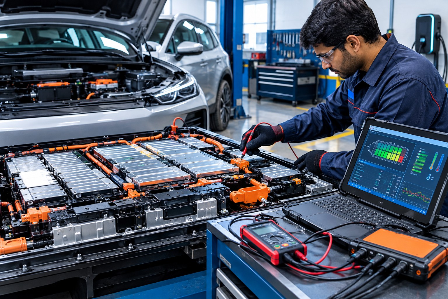
Electric Vehicle (EV) battery diagnostics is the process of checking the battery pack, individual cells, electrical connections, temperature sensors, insulation, voltage readings, and Battery Management System (BMS) to determine the actual condition of the battery.
The BMS is one of the most important electronic systems in an EV because it continuously monitors battery voltage, current, temperature, state of charge (SOC), and other operating parameters. When a battery-related fault occurs, proper diagnostics can help identify whether the problem is caused by a weak cell, sensor, wiring, communication issue, charging system, or the BMS itself.
Because EV battery packs can contain high-voltage electrical energy, diagnostic work should only be performed with the correct equipment, training, and manufacturer-approved safety procedures.
What Is EV Battery Diagnostics?
EV battery diagnostics involves measuring and analyzing different parameters of the high-voltage battery system.
A typical diagnostic process may include:
- Battery pack voltage inspection
- Individual cell or module voltage comparison
- State of charge (SOC) analysis
- State of health (SOH) evaluation
- Battery temperature monitoring
- Current measurement
- Insulation resistance testing
- BMS fault-code analysis
- CAN communication diagnosis
- Connector and wiring inspection
- Charging and discharging performance evaluation
The objective is not simply to determine whether the battery works. A proper diagnostic procedure attempts to identify the specific reason for abnormal battery behavior.
Understanding the EV Battery Pack
An EV battery pack is normally made from multiple battery cells connected in series and parallel configurations.
Individual cells are grouped into modules, and multiple modules are combined to form the complete battery pack.
The battery system can therefore be viewed as:
Cell → Module → Battery Pack → BMS → Vehicle Control Systems
Depending on the vehicle design, the battery pack may also contain contactors, current sensors, temperature sensors, fuses, service disconnects, cooling components, and high-voltage connectors.
A problem in any of these components can affect vehicle performance.
What Is a Battery Management System (BMS)?
The Battery Management System is the electronic control system responsible for monitoring and managing the battery.
Its functions can include:
- Monitoring cell voltages
- Monitoring battery temperature
- Measuring battery current
- Calculating SOC
- Estimating SOH
- Detecting abnormal conditions
- Controlling battery charging limits
- Managing discharge limits
- Controlling contactors
- Protecting against overvoltage
- Protecting against undervoltage
- Protecting against excessive temperature
- Communicating with other vehicle control modules
The exact BMS architecture varies between EV manufacturers and battery platforms.
Why BMS Testing Is Important
A battery pack can sometimes show a normal overall voltage while still having a problem with one or more cells.
For example, if most cells are operating within a similar voltage range but one cell group consistently behaves differently, the BMS may detect a cell imbalance or abnormal voltage condition.
BMS testing helps identify these differences.
It can also help determine whether a fault is related to:
- Battery cells
- Voltage sensing circuits
- Temperature sensors
- Current sensors
- BMS communication
- Wiring harnesses
- Connectors
- Contactors
- Software or calibration
- External charging systems
Important EV Battery Parameters
1. Cell Voltage
Cell voltage is one of the most important diagnostic parameters.
The BMS normally monitors individual cell groups or modules. During diagnosis, technicians compare the readings rather than relying only on total battery voltage.
A significant difference between cell-group readings may indicate:
- Cell imbalance
- A weak cell group
- High internal resistance
- Connection resistance
- Measurement circuit problems
The acceptable voltage range depends on the battery chemistry, state of charge, temperature, and manufacturer specifications.
2. Battery Pack Voltage
Total pack voltage is measured by combining the voltage of the connected cell groups.
A diagnostic scan tool may display pack voltage electronically through the BMS.
If the measured voltage does not agree with the expected value, the cause may be related to the battery itself, voltage sensing, contactors, wiring, or measurement equipment.
3. State of Charge (SOC)
SOC represents the estimated amount of usable energy remaining in the battery.
It is similar to the fuel-level concept in a conventional vehicle, but the calculation is more complex.
The BMS can estimate SOC using information such as:
- Battery current
- Voltage
- Temperature
- Previous battery conditions
- Charging and discharging history
- Battery model calculations
SOC should not be interpreted as a direct measurement of battery health.
4. State of Health (SOH)
SOH provides an estimate of the battery’s remaining capacity or performance compared with its reference condition.
Battery aging can cause:
- Reduced capacity
- Increased internal resistance
- Increased voltage variation under load
- Reduced charging performance
- Reduced driving range
SOH calculation methods differ between manufacturers and BMS designs.
Therefore, a scan-tool SOH value should be interpreted according to the vehicle manufacturer’s diagnostic procedures.
5. Battery Temperature
Temperature has a major effect on battery performance and safety.
The BMS monitors temperature sensors distributed throughout the battery system.
An abnormal temperature reading may indicate:
- Sensor failure
- Wiring problems
- Cooling-system problems
- Localized battery heating
- Charging or operating conditions outside the expected range
Temperature readings should always be compared with the manufacturer’s specifications and with other sensors in the pack.
EV Battery Diagnostic Equipment
Professional EV diagnostics may require several types of equipment.
Diagnostic Scan Tool
A compatible diagnostic scanner can communicate with vehicle control modules and display:
- BMS fault codes
- Cell voltages
- Battery temperatures
- SOC
- SOH
- Pack current
- Pack voltage
- Contactor status
- Charging-related parameters
A generic OBD scanner may not provide complete high-voltage battery information. Manufacturer-specific diagnostic equipment may be required.
Digital Multimeter
A suitable CAT-rated multimeter can be used for electrical measurements where permitted by the manufacturer’s service procedure.
The meter must be appropriate for the voltage category and measurement task.
Insulation Resistance Tester
An insulation tester can be used to evaluate electrical isolation between the high-voltage system and the vehicle chassis.
Insulation testing procedures vary by vehicle and battery architecture. Incorrect testing voltage or procedure can damage electronic components.
Current Measurement Equipment
Current sensors or appropriate measurement equipment can help evaluate battery charging and discharging behavior.
High-current measurements require equipment designed for the expected current and voltage.
Thermal Imaging Camera
A thermal camera can sometimes help identify abnormal heat patterns around:
- Battery connections
- Busbars
- Contactors
- Cables
- Cooling components
Thermal inspection is an additional diagnostic method and does not replace electrical measurements or manufacturer procedures.
Step-by-Step EV Battery Diagnostic Process
Step 1: Follow High-Voltage Safety Procedures
Before any diagnostic work, identify the vehicle’s high-voltage system and follow the manufacturer’s shutdown and isolation procedure.
Do not assume that switching the vehicle off makes the battery system safe.
High-voltage batteries can retain dangerous energy even when the vehicle is not operating.
Use the required PPE, insulated tools, approved test equipment, and isolation procedures.
Step 2: Perform a Visual Inspection
Inspect the battery system for visible abnormalities.
Check for:
- Damaged high-voltage cables
- Corroded connectors
- Loose connections
- Physical battery damage
- Signs of overheating
- Coolant leakage
- Water intrusion
- Damaged wiring
- Connector contamination
Do not continue testing if there is evidence of serious battery damage or another unsafe condition.
Step 3: Scan the BMS for Fault Codes
Connect the appropriate diagnostic tool and retrieve stored and active fault codes.
Do not immediately erase fault codes.
Record the codes and their associated data first.
Look for faults related to:
- Cell voltage
- Temperature
- Insulation
- Current sensing
- Communication
- Contactor operation
- Charging
- Battery management
The diagnostic code should be interpreted using the manufacturer’s service information.
Step 4: Check Cell Voltage Data
Review individual cell-group voltages through the diagnostic system if available.
Compare the readings under similar conditions.
A single abnormal reading does not automatically prove that the cell itself is defective. The sensing harness, connector, busbar, or BMS measurement circuit can also cause an abnormal reading.
Step 5: Compare Temperature Sensors
Review all available battery temperature readings.
Look for:
- One sensor showing an unrealistic value
- Significant temperature differences
- Temperature increases during charging or load
- Temperature-related BMS warnings
Sensor readings should be compared with ambient conditions and manufacturer specifications.
Step 6: Check Battery Current
Battery current information can help identify charging and discharging behavior.
Compare the BMS-reported current with the expected operating condition.
If the reading appears unrealistic, possible causes may include:
- Current sensor problems
- Wiring faults
- Communication problems
- BMS calculation issues
Step 7: Check BMS Communication
Modern EVs use communication networks such as CAN to exchange information between the BMS and other vehicle control modules.
Communication problems can produce symptoms such as:
- Battery warning messages
- Charging failure
- Reduced power
- Incorrect battery information
- Vehicle not entering READY mode
A CAN-related fault does not necessarily mean that the BMS control unit itself is defective.
The wiring, connectors, power supply, ground, termination, or another control module may be responsible.
Step 8: Evaluate Insulation
High-voltage insulation is critical for vehicle safety.
The system must maintain adequate electrical isolation between high-voltage conductors and the vehicle chassis.
If an insulation fault is detected, possible causes can include:
- Damaged cable insulation
- Moisture
- Coolant contamination
- Battery casing problems
- Component insulation failure
- Charging-system faults
Use only the manufacturer’s specified test procedure because improper insulation testing can damage sensitive electronics.
Step 9: Check Contactors and Pre-Charge Operation
High-voltage battery packs commonly use contactors to connect and disconnect the battery from the vehicle’s high-voltage circuit.
A pre-charge circuit may also be used to control the initial charging of capacitors in the high-voltage system.
Faults in this area can cause:
- No READY condition
- Charging problems
- High-voltage system shutdown
- Contactor-related fault codes
Diagnosis should include the relevant BMS data and manufacturer test procedures.
How to Identify a Weak Battery Cell
A weak cell or cell group may not always be obvious when the battery is at rest.
A better diagnosis considers how the cell behaves during charging and discharging.
A potentially weak cell group may:
- Drop in voltage faster under load
- Reach the upper voltage limit earlier during charging
- Show greater voltage deviation from other groups
- Cause repeated BMS imbalance warnings
- Contribute to reduced usable capacity
However, voltage variation alone is not enough to confirm a defective cell.
Battery temperature, SOC, current, internal resistance, and BMS calculations should also be considered.
Battery Cell Balancing
Cell balancing helps keep individual cell groups within an acceptable voltage relationship.
There are two common approaches:
Passive balancing: excess energy is dissipated as heat through balancing circuits.
Active balancing: energy can be transferred between cells or cell groups.
The actual balancing strategy depends on the BMS design.
If one cell group repeatedly becomes imbalanced, simply forcing a balance may not solve the underlying problem. The battery may have a degraded cell, increased resistance, or another electrical fault.
Common EV Battery and BMS Faults
Cell Voltage Imbalance
Possible causes include:
- Cell aging
- Capacity differences
- High internal resistance
- Poor connections
- Cell sensing problems
Temperature Sensor Fault
Possible causes include:
- Failed sensor
- Damaged wiring
- Connector problems
- BMS input fault
Insulation Fault
Possible causes include:
- Damaged insulation
- Moisture
- Coolant contamination
- High-voltage component failure
BMS Communication Fault
Possible causes include:
- CAN wiring problems
- Poor connectors
- Power supply issues
- Ground problems
- Network termination issues
- Control-module failure
Charging Failure
Charging problems can originate from several systems, including:
- BMS
- On-board charger
- Charging connector
- High-voltage contactors
- Temperature conditions
- Battery protection logic
- Communication between vehicle modules
A charging failure should therefore not automatically be blamed on the battery pack.
EV Battery Diagnostic Mistakes to Avoid
Several mistakes can create additional problems during EV diagnosis.
Do Not Measure High Voltage With Unsuitable Equipment
Always use equipment rated for the voltage and measurement category involved.
Do Not Ignore Isolation Procedures
A high-voltage battery must be treated as energized until the manufacturer’s isolation and verification procedure confirms otherwise.
Do Not Replace the BMS Without Diagnosis
Replacing an expensive BMS without proving that it is faulty can waste time and money.
Do Not Judge Battery Health From Pack Voltage Alone
A normal total voltage does not prove that every cell group is healthy.
Do Not Ignore Temperature Data
Temperature abnormalities can be an important clue to battery, cooling, sensor, or charging problems.
Battery Diagnostics During Charging
Charging is an important opportunity to observe battery behavior.
Depending on the vehicle and diagnostic equipment, technicians may monitor:
- Charging current
- Pack voltage
- Cell voltage differences
- Battery temperature
- SOC
- Charging power
- Contactor status
- BMS warnings
If one cell group behaves abnormally during charging, further diagnosis may be required.
Battery Diagnostics During Load
Battery behavior under load can reveal problems that may not appear during a static voltage check.
Under acceleration or another controlled load condition, a weak cell group may experience a larger voltage drop than healthier groups.
However, load testing on an EV must be performed according to the manufacturer’s procedure and appropriate safety requirements.
When Battery Replacement May Be Necessary
Battery replacement should not be the first conclusion after finding a battery-related fault.
Depending on the diagnosis, the repair may involve:
- Wiring repair
- Connector repair
- Sensor replacement
- Cooling-system repair
- BMS-related repair
- Cell or module replacement where supported
- Contactor replacement
- Charging-system repair
The battery pack may require replacement when the manufacturer determines that the pack or a major internal component has reached a condition where repair is not permitted or economically practical.
Importance of Manufacturer Service Information
EV battery systems are not identical.
Battery chemistry, voltage levels, BMS architecture, communication systems, cell configuration, cooling systems, diagnostic procedures, and allowable repair methods can differ substantially between vehicles.
For this reason, exact voltage limits, insulation limits, torque specifications, balancing procedures, isolation steps, and component replacement procedures should always come from the correct manufacturer service documentation.
EV Battery Diagnostics and Preventive Maintenance
Regular maintenance can help identify problems before they become severe.
Useful practices include:
- Monitoring unusual charging behavior
- Paying attention to battery warning messages
- Keeping cooling systems maintained
- Checking for physical damage
- Inspecting charging equipment
- Following recommended service intervals
- Using appropriate diagnostic equipment when faults appear
Drivers should also avoid ignoring repeated battery warnings or unusual changes in charging performanceRead also how-to-change-bike-wheel-bearings
Conclusion
Electric Vehicle battery diagnostics and BMS testing require a systematic approach. Checking only the overall battery voltage is not enough to determine battery condition.
A proper diagnostic process evaluates cell-group voltage, temperature, current, SOC, SOH, insulation, BMS communication, contactors, charging behavior, and fault codes.
The most important principle is to diagnose the actual cause rather than replacing expensive battery components based only on symptoms.
Because EV battery packs operate at potentially hazardous high voltages, internal battery repair and high-voltage testing should be performed only by appropriately trained personnel using approved equipment and the vehicle manufacturer’s procedures.
Rajesh Technical Gyan
1 thought on “How to Diagnose EV Battery & Test BMS: Step-by-Step”